This heavy-duty, high-engineering homebrew project is optimized for extreme durability and continuous operation in demanding radio amateur contest and DX hunting environments.
1. Design Philosophy & Core Capabilities
- Four-Module Architecture: To comfortably deliver a continuous 1.5 kW output (full legal limit) with ultimate thermal headroom, the design distributes the total power load across four independent ART1K6 LDMOS transistor modules.
- Sub-Harmonic Loading: Each LDMOS module is driven to output under 400 W, even though a single ART1K6 device is rated for over 1 kW. This vast safety margin prevents component degradation and handles high VSWR conditions safely.
- Frequency Range: Complete coverage of all high-power HF amateur bands from 160 m to 10 m.
- Mechanical Footprint: The fully integrated chassis weighs approximately 30 kg and includes heavy-duty carrying handles.
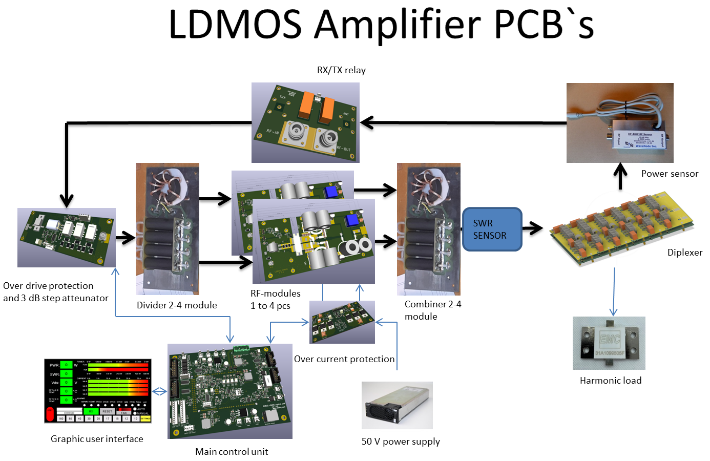
2. Technical System Structure & Modules
The amplifier is partitioned into specialized sub-assemblies and circuit boards to ensure isolated signal paths and coordinated system logic:
RF Power Stages & Power Combining
- RF Modules: Four identical LDMOS pallet boards. The ART1K6 transistors are directly reflow-soldered onto thick copper heat spreaders, which are bolted securely onto a massive aluminum heatsink assembly.
- Divider & Combiner Networks: Incoming RF drive power is split evenly among the four modules, and their individual outputs are reconstituted into a single line through high-power hybrid combining networks before filtering.
6-Band HF Diplexer System
- Working Principle: Unlike standard low-pass filters (LPF) that reflect out-of-band harmonics back to the source, this amplifier deploys dedicated diplexers. Push-pull LDMOS topologies inherently generate strong 3rd-harmonic spikes that can measure just 10 to 12 dB below the fundamental signal carrier.
- Harmonic Load Management: Instead of bouncing these dangerous harmonic spikes back into the sensitive FETs (causing thermal stress), the diplexer routes the clean fundamental signal directly to the antenna and diverts the harmonic energy (up to 150 W at full legal limit) into an isolated, fan-cooled dummy load (harmonic load).
- Attenuation Metrics: The 3rd harmonic is suppressed to -50 dB @ 2 kW. A WaveNode SWR sensor is integrated inline for tracking.
System Control & Hardware Protection
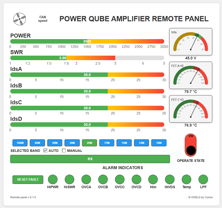
- Control Board: A management motherboard compatible with both the Arduino DUE and the Arduino Giga WiFi. The Giga platform unlocks browser-based telemetry.
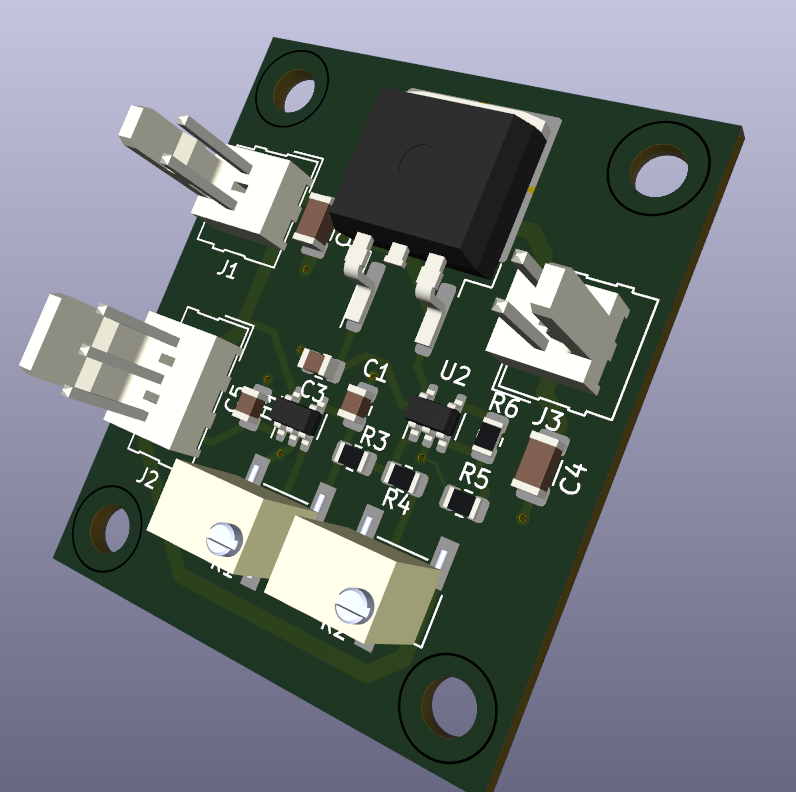
- LDMOS Power Switch: A dedicated, ultra-fast Over-Current Protection (OCP) circuit board that disconnects the main high-voltage rail within milliseconds during a current spike.
- Input Step Attenuator: An inline RF step attenuator system that absorbs excessive transceiver output, ensuring the sensitive LDMOS gate junctions are never over-driven.
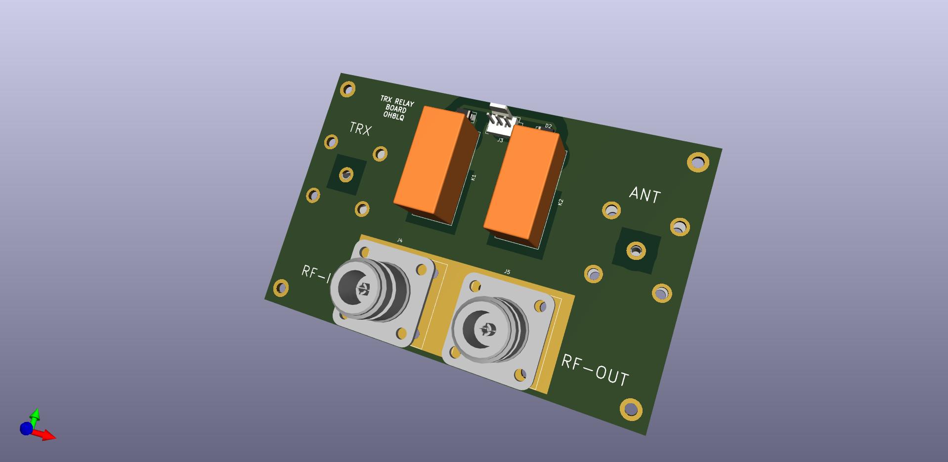
- TRX-Relay Board: Handles fast, sequence-timed transmit/receive relay state transitions.
- Fan Speed Controller: A dedicated module reading localized thermal metrics via LM35 sensors to dynamically scale cooling fan noise and performance.
3. Three-Phase Power Supply Units (PSU)
Generating 3 kW of continuous RF carrier requires between 6 kW to 9 kW of clean DC current. Sourcing this from a standard single-phase residential mains outlet could risk unbalanced phase loads and blown circuit breakers. The power grid input is therefore split across a 3-phase system.
The project outlines two interchangeable modular options:
- HP ESP120 Configuration: Three server-grade power supplies configured across three input phases, delivering a highly stabilized 50 V rail at 9 kW total output capability.
- Huawei R4850G2 Configuration: Three high-efficiency Huawei rectifiers running in a parallel configuration. This setup uses a CAN bus matrix routed over a D15 connector to command voltage adjustments and enforce systemic safety shutdowns.
4. User Interface (UI)
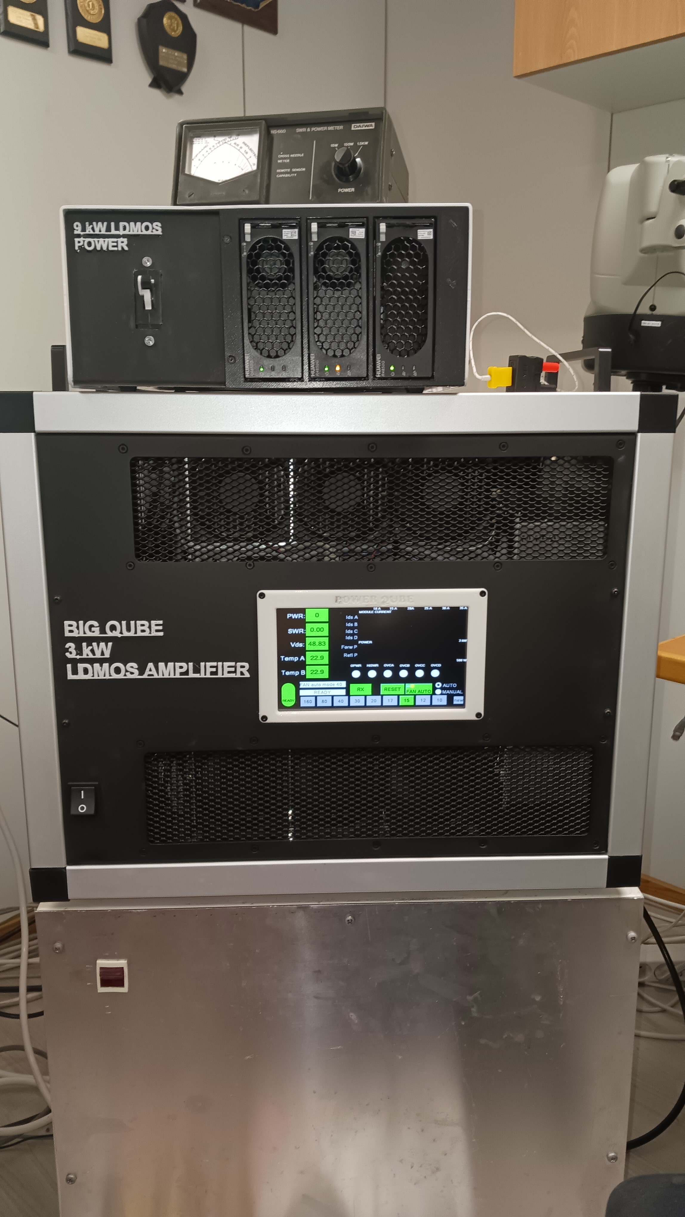
- Local UI Control: The amplifier uses a front-panel Nextion TFT touchscreen display for local desktop interaction.
- Remote monitoring: Using an Arduino Giga board with a controller card provides a browser-based Java remote user interface.
PCB Availability for Builders
For radio amateurs looking to reproduce parts of this build, the web page notes that blank or partially pre-assembled SMD circuit boards (such as the over-current protection modules) are available for purchase directly from OH8LQ. For example, the ready-assembled SMD power protection board is priced at 48.00 EUR plus shipping.
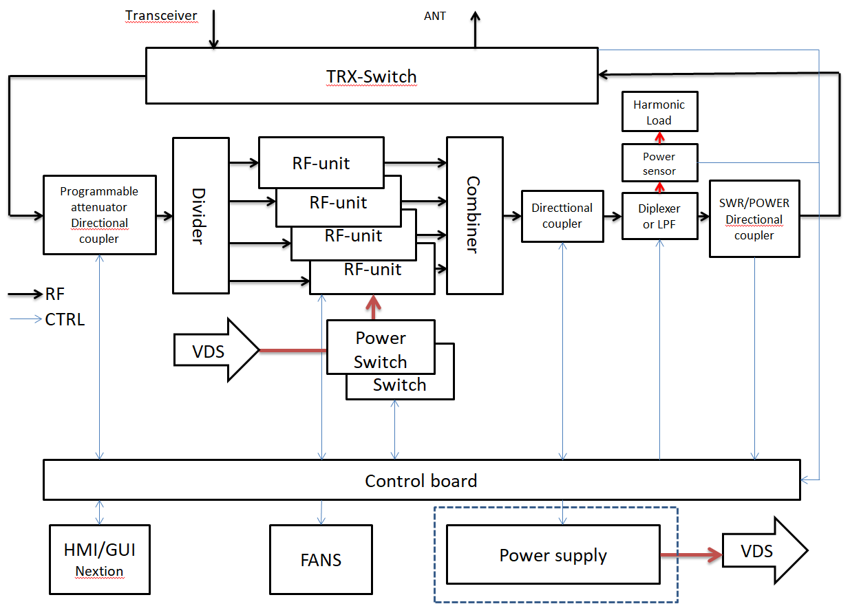
BLOCK DIAGRAM
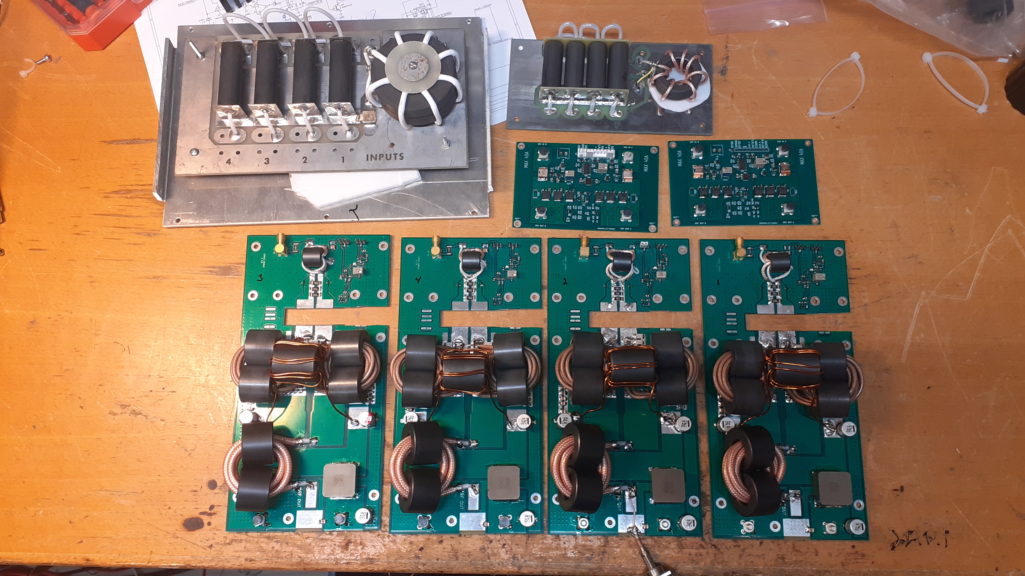
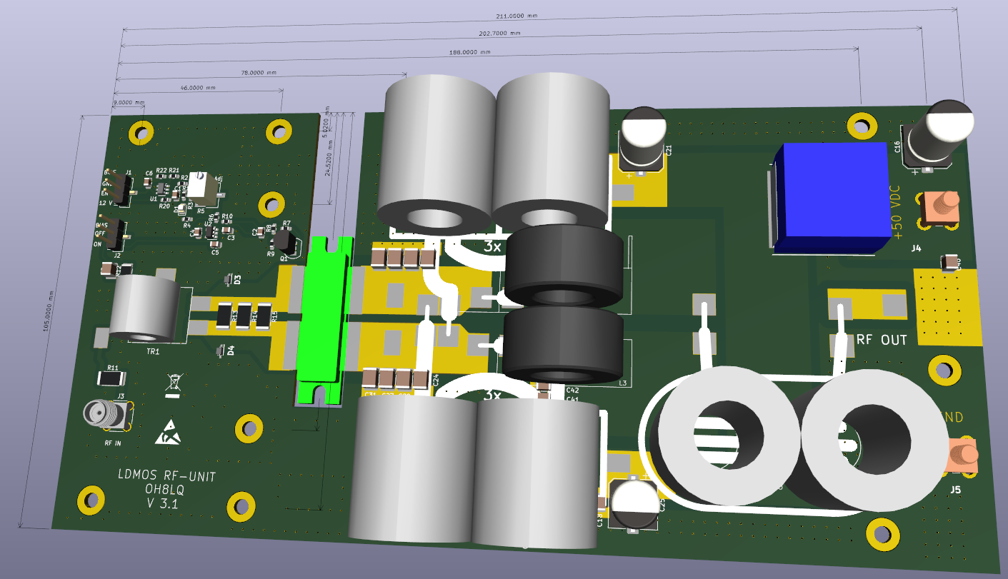
Circuit boards of the RF part
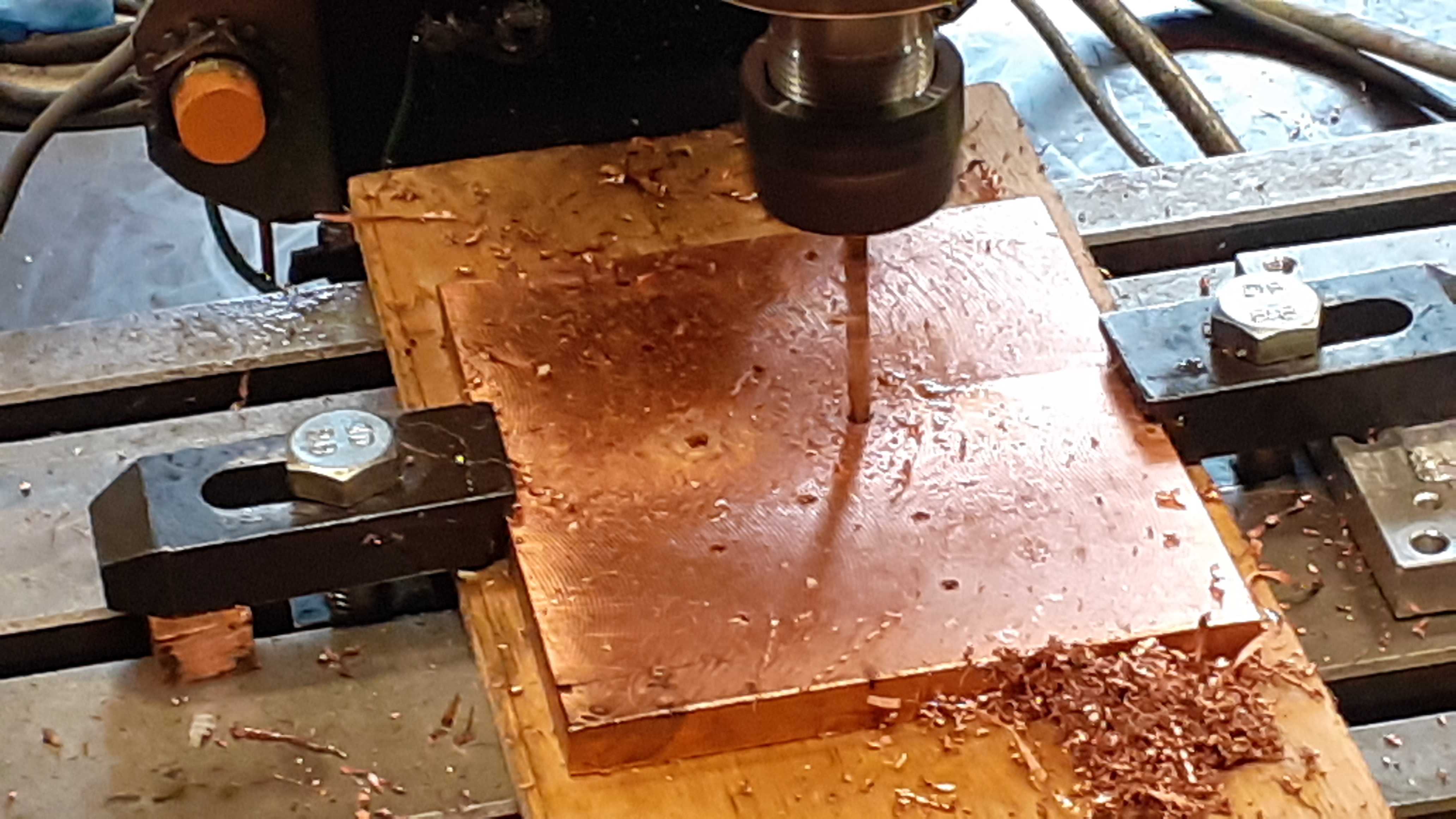
Drilling holes in copper plate
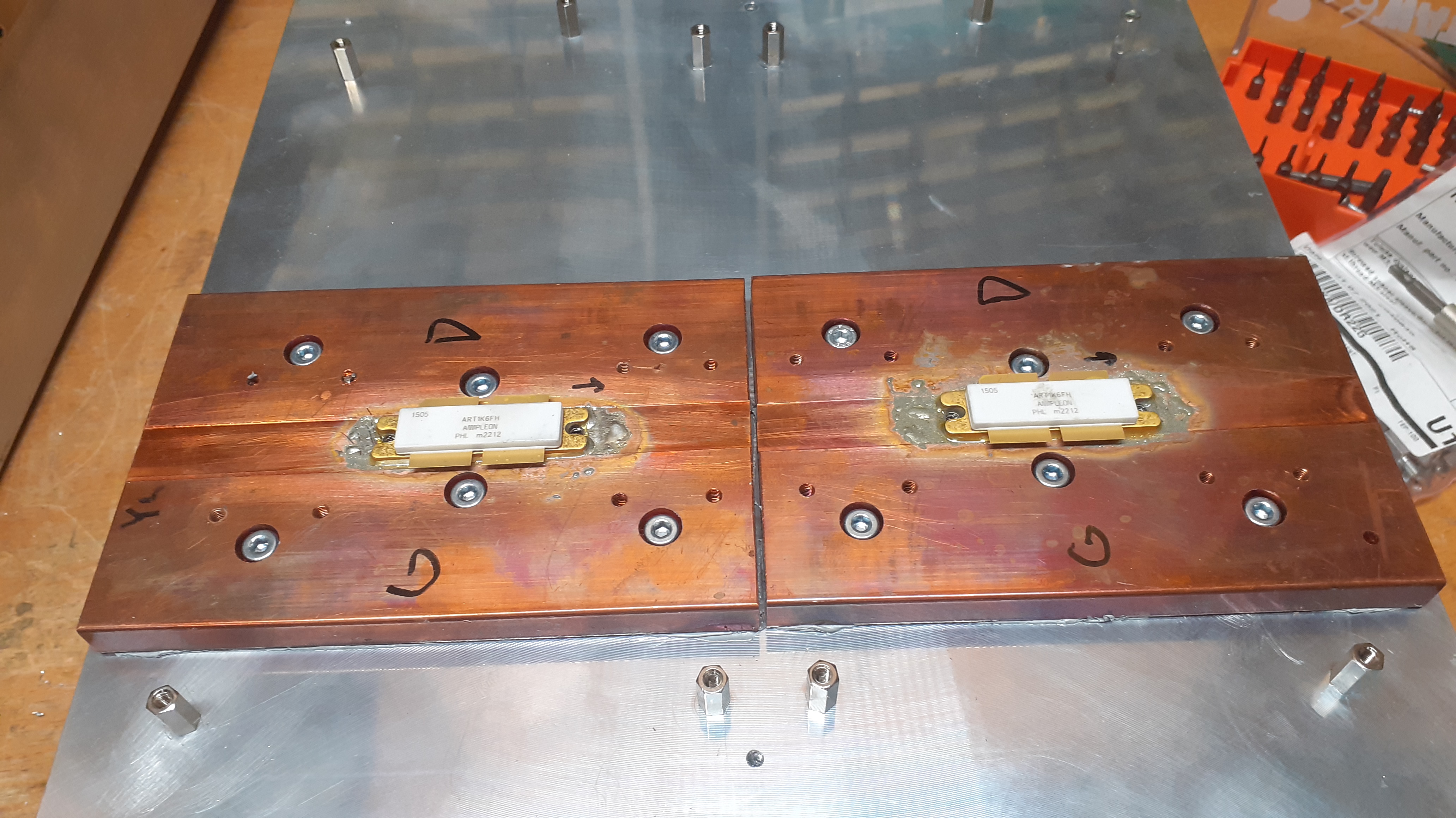
- ART1K6 Transistors: Two of the four total transistors used in the project are shown here, seated into milled pockets inside the copper blocks.
- Solder Joint: Devices are directly soldered to the copper blocks rather than mounted using thermal paste and screws. Direct soldering provides the lowest possible thermal resistance, which is vital when moving hundreds of watts of waste heat away from a tiny silicon die.
- Copper Heat Spreaders: Copper conducts heat significantly faster than aluminum. Because the surface area of an LDMOS die is extremely small, the copper spreader diffuses the concentrated heat outward over a larger surface area before it passes into the underlying aluminum cooling profile.
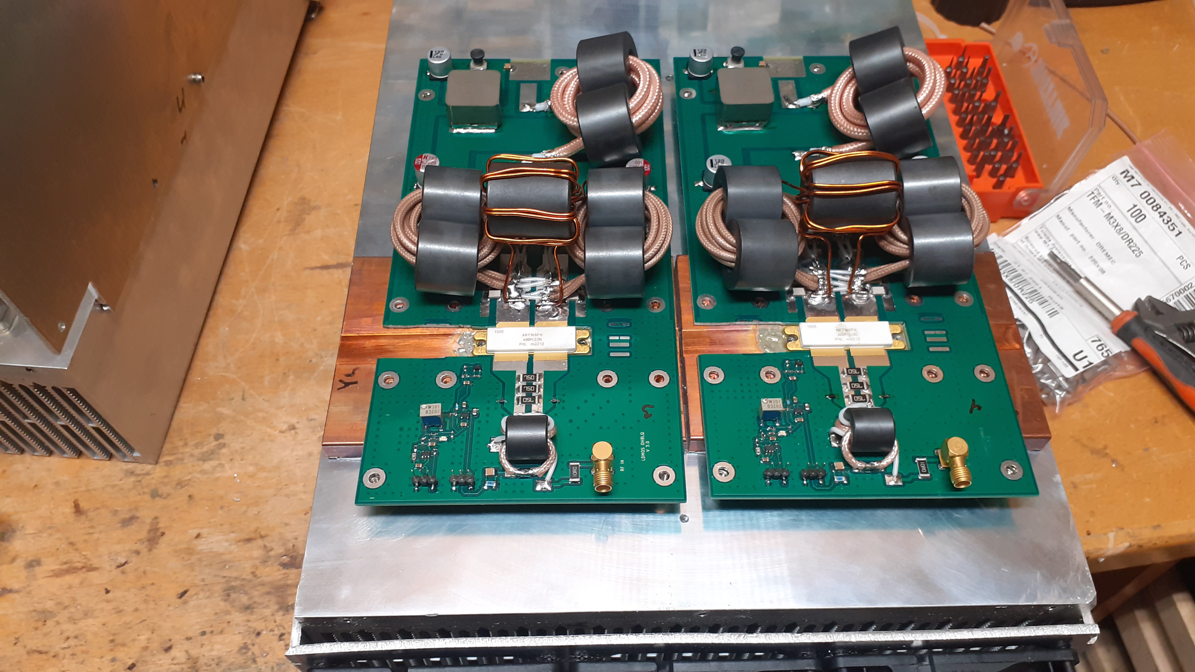
- RF Circuit Boards (Pallets): The printed circuit boards are overlaid precisely onto the copper heat spreaders so that the ART1K6 transistors emerge through the milled cutouts in the center. The transistor gate and drain leads are securely soldered directly onto the PCB traces.
- Impedance Matching Transformers (Coaxial Cables and Ferrites):
- Input Section (Bottom): Smaller coax lines running through ferrite beads alongside SMD capacitor networks step down the standard 50-ohm transceiver drive line to match the extremely low input impedance of the LDMOS gates. RF input is fed to each board via brass SMA connectors.
- Output Section (Top): Heavy-duty, thick Teflon-insulated coaxial cables routed through large ferrite output transformers. These transform the ultra-low output impedance of the LDMOS drains back up to a higher level so the modules can be combined toward a standard 50-ohm antenna system.
- Main DC Power Distribution (Top Corners): Wide copper traces combined with high-capacity electrolytic decoupling capacitors are positioned at the top corners of the PCBs to supply the heavy 50 VDC operating current demanded by the transistors during transmission.
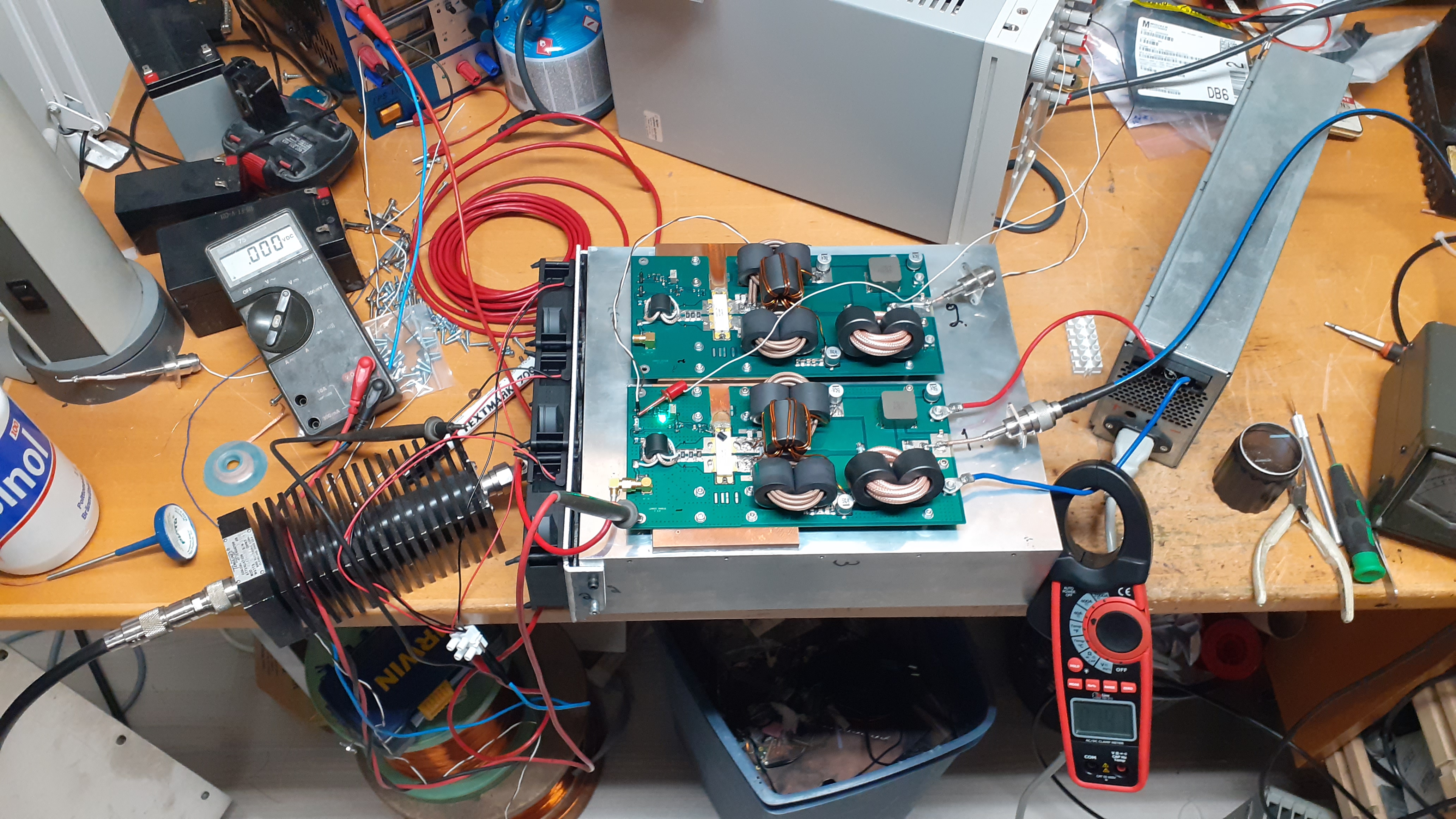
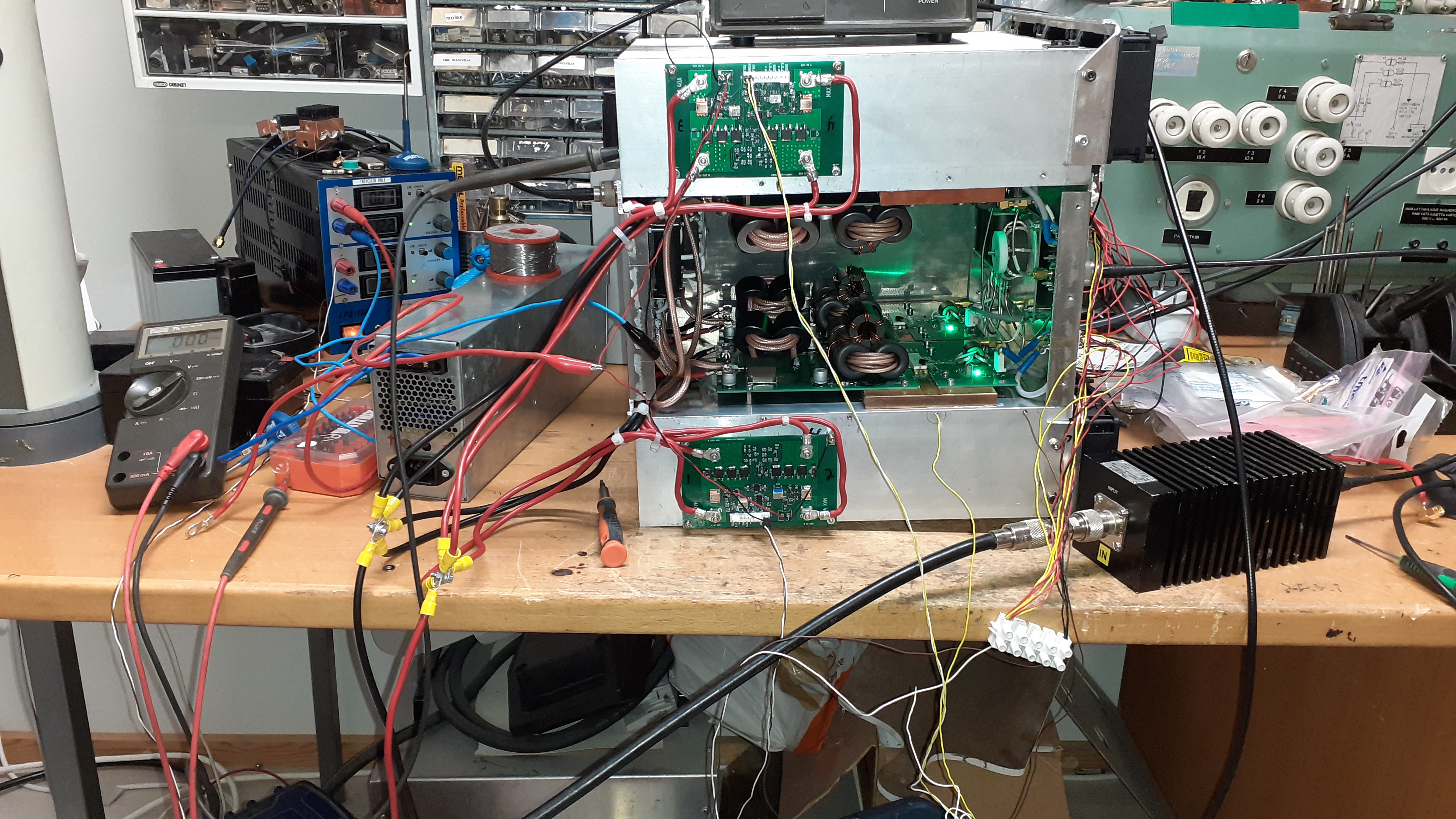
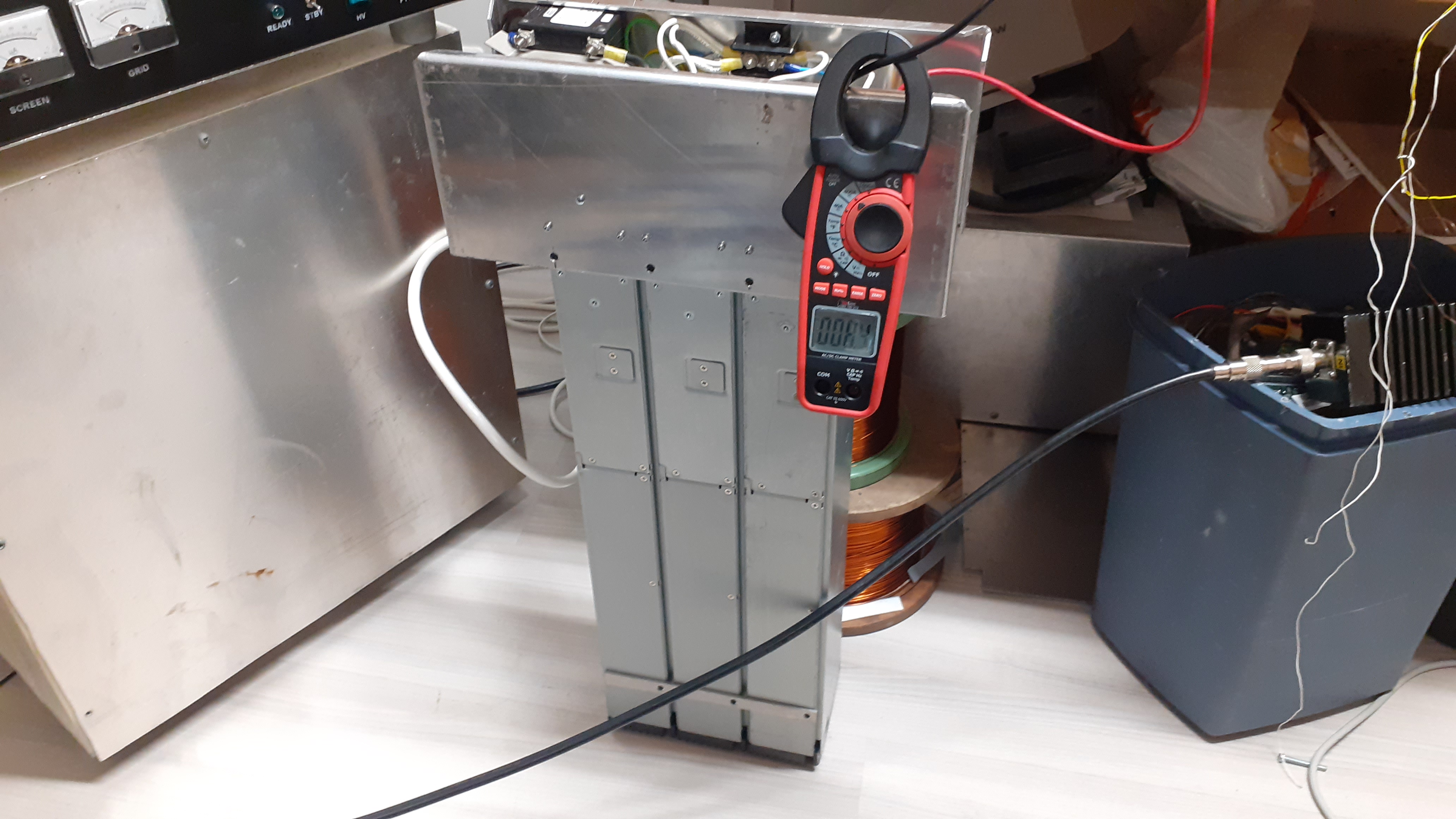
Each module is tested separately
Latest version RF-module
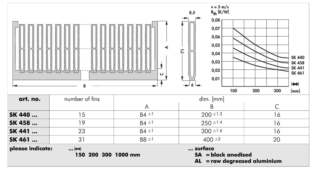
Heat sink datasheet
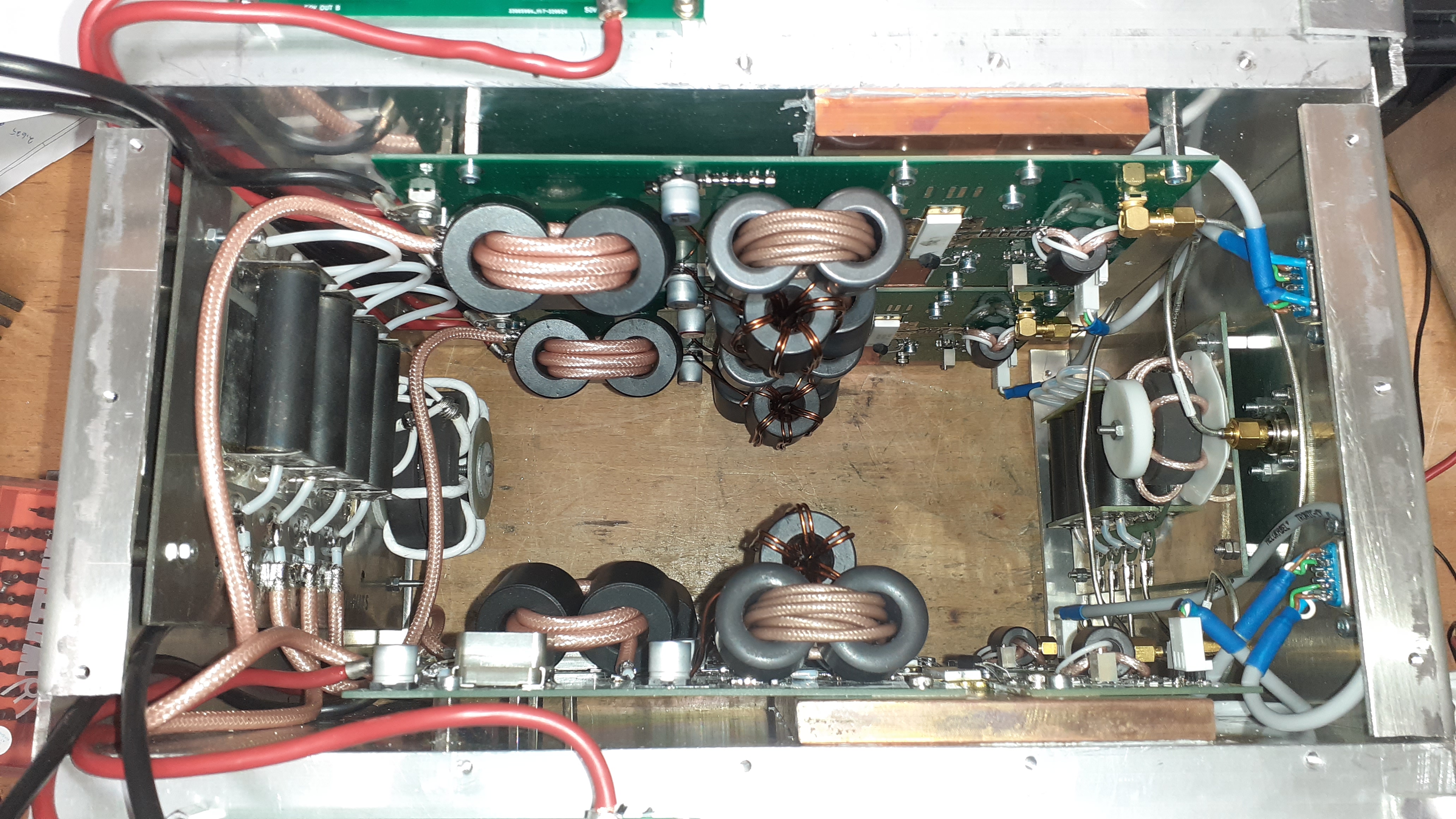
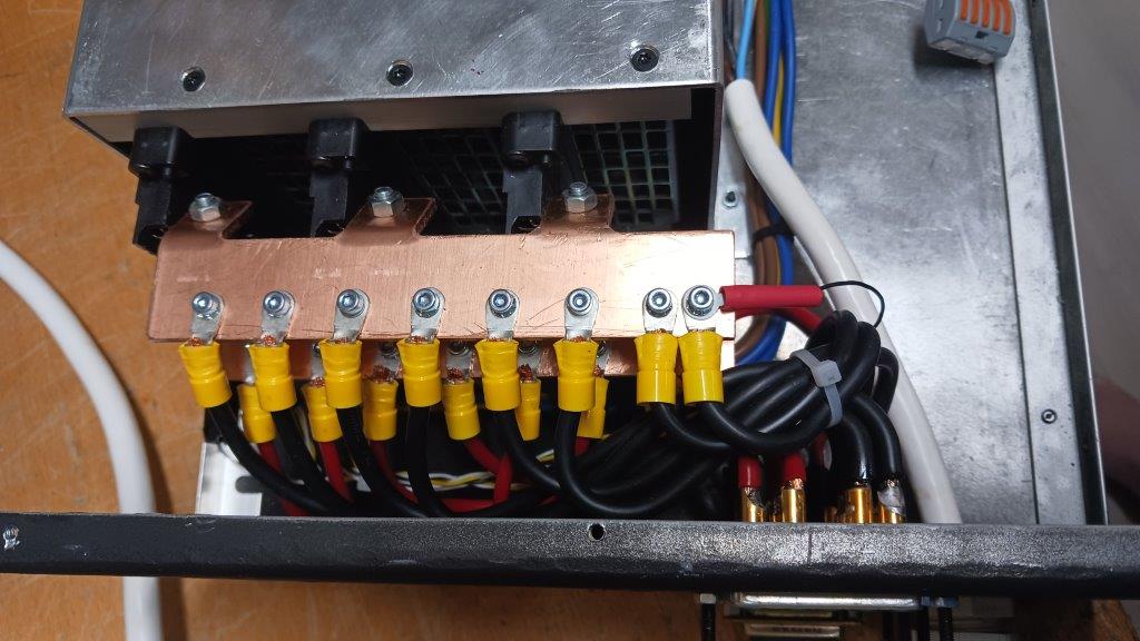
Four modules with heatsink and combiner and divider
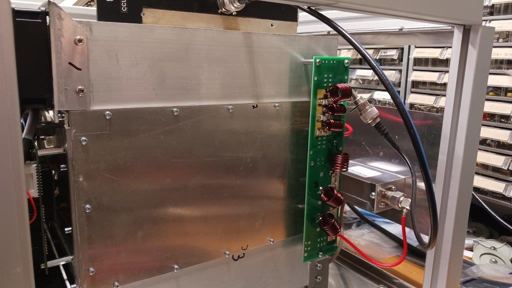
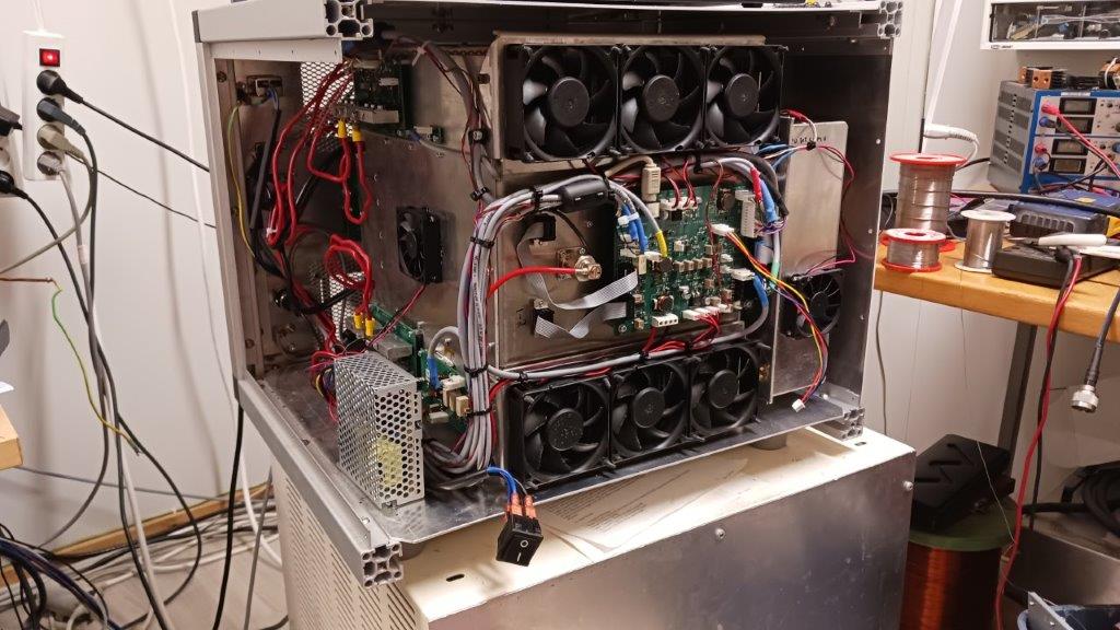
RF amplifier unit and power switches
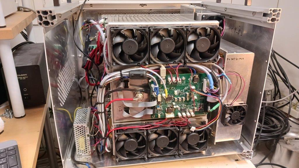
- Central Power Stage Cooling Tunnel:
- The core features a massive aluminum heatsink block where the internal LDMOS power pallets are bolted.
- To maintain optimal airflow, a six-fan cooling matrix forces continuous high-velocity air straight through the cooling fins.
- System Controller Unit (Green PCB, Center-Left):
- The amplifier's Control Board motherboard is mounted vertically onto the side of the cooling tunnel structure.
- It interfaces with an extensive array of ribbon cables and sensor lines, aggregating analog telemetry (such as individual module drain currents and localized thermal metrics) and distributing timing commands to the relay matrices.
- Auxiliary Power & Distribution Subsystem (Left Margin):
- A small auxiliary power supply protected by a perforated metal cage sits in the lower left corner, generating lower-voltage rails (typically 12V and 5V) to run the cooling fans and digital logic.
- Directly above it run heavy-gauge red and black high-current DC power cables, carrying the primary 50V supply rail from the external 3-phase rectifiers directly to the LDMOS transistor pallets.
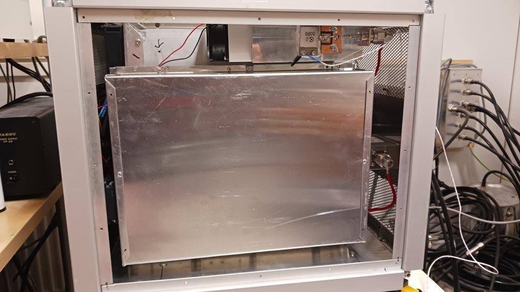
- Shielded Diplexer Enclosure (Right Margin):
- The right side features a dedicated RF compartment fully enclosed in metal shielding sheets to minimize electromagnetic interference (EMI).
- This shielded cage protects the high-power multi-band diplexer filter networks and houses the specialized harmonic dummy load, which is cooled independently by an auxiliary fan mounted directly to the side of the enclosure.
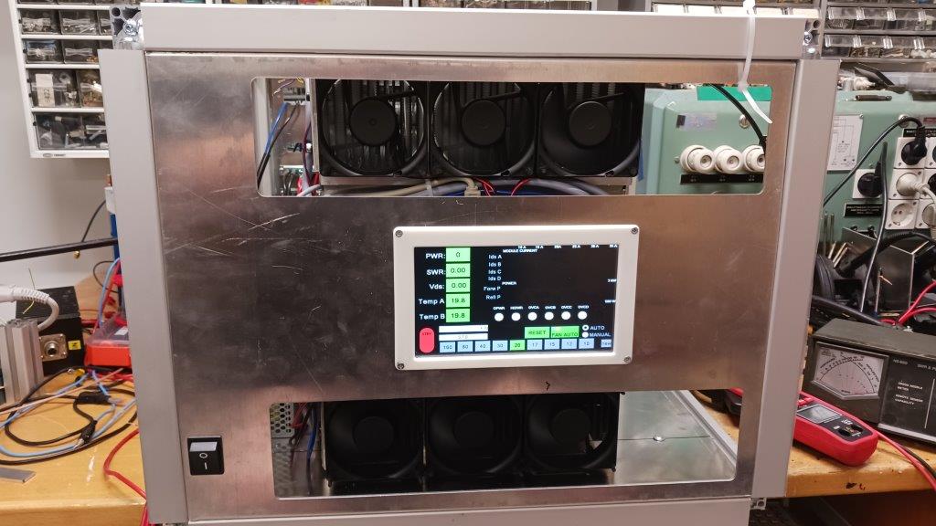
UI at rear panel
DIPLEXERS
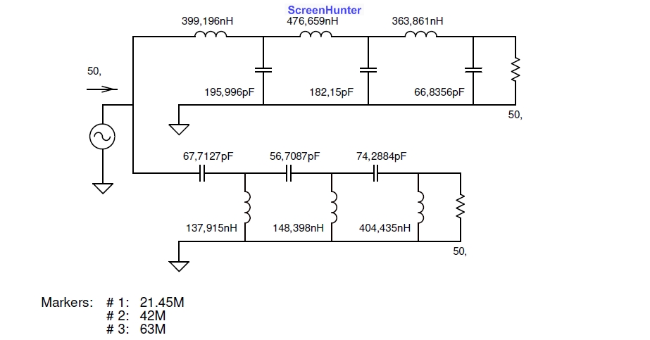
Diplexer calculations: 160 m 80 m 40 m 20 m 15 m 10 m
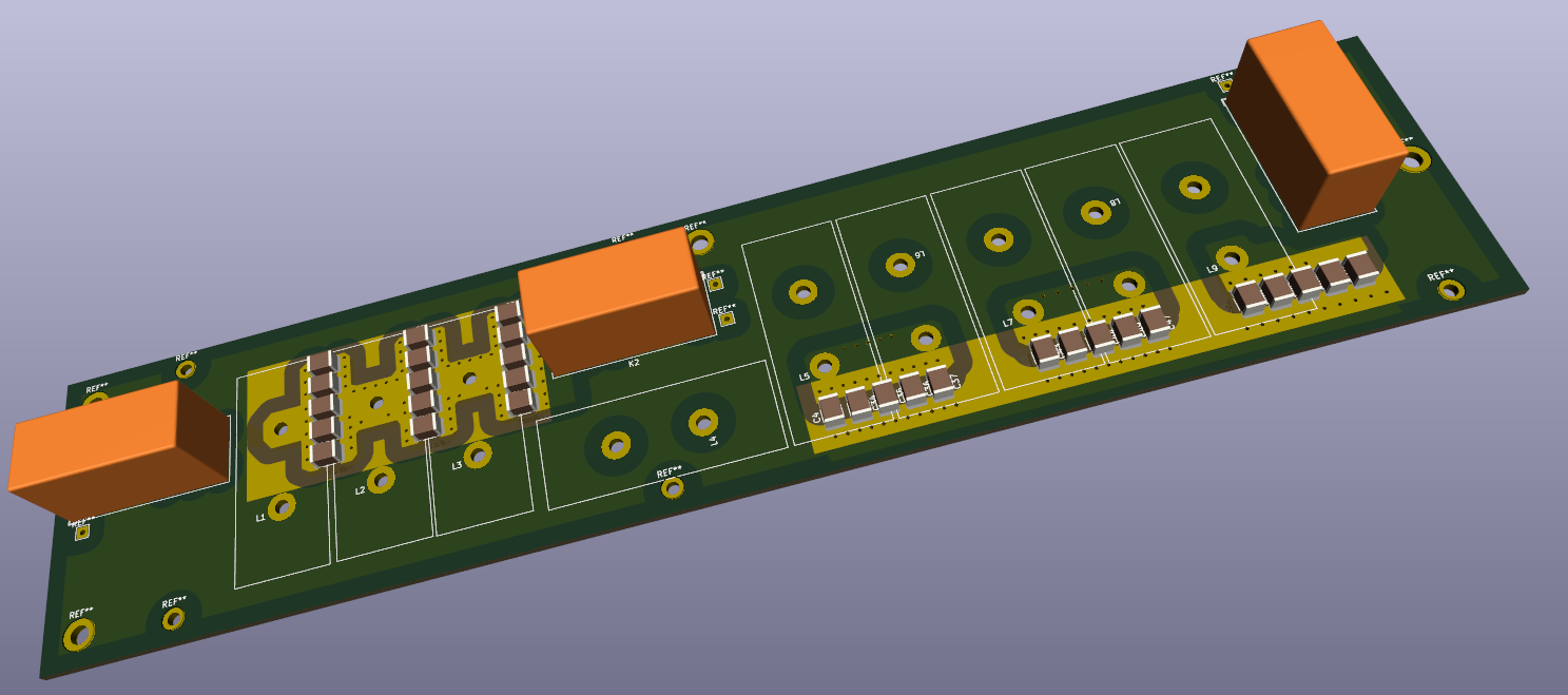
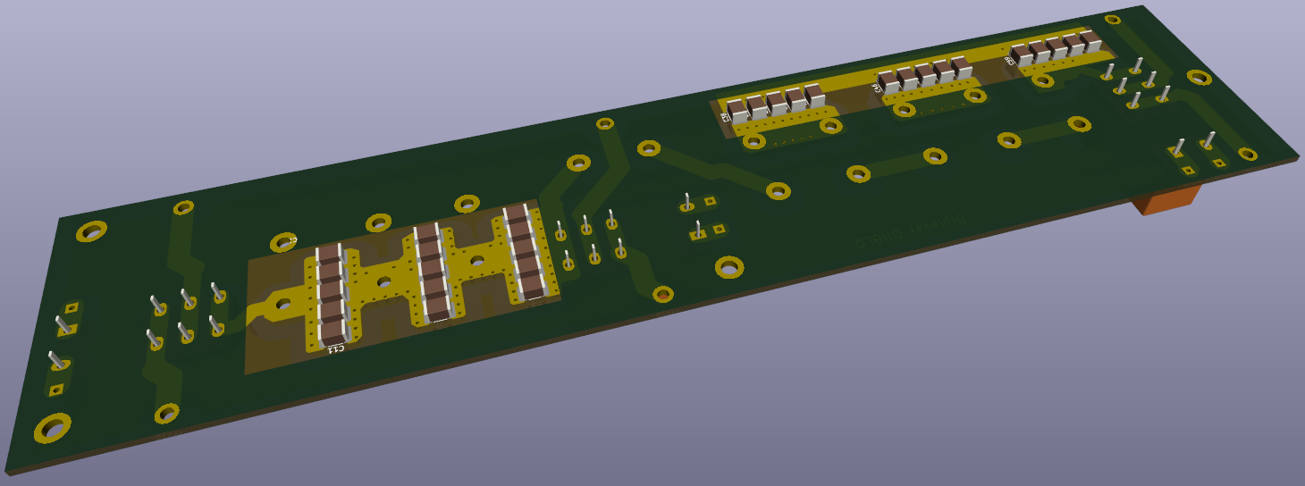
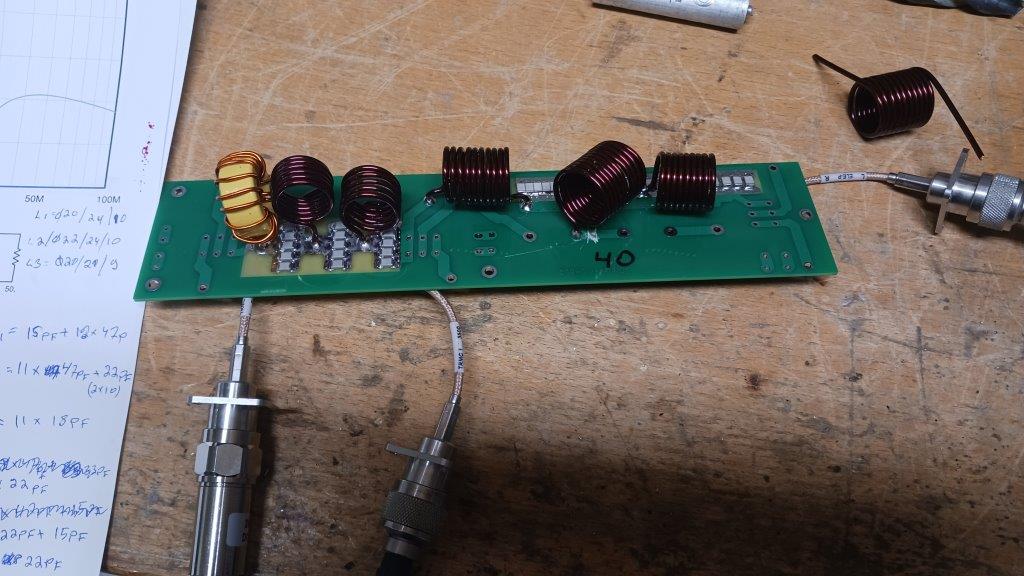
New diplexer board
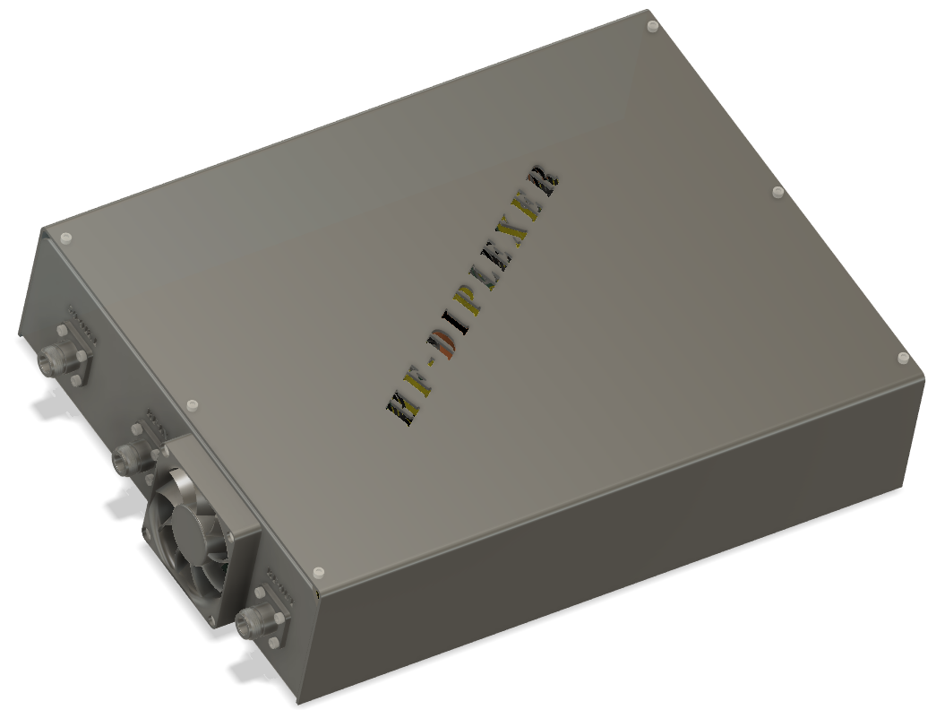
External diplexer box (playing with Fusion360) https://a360.co/44MIS8Y
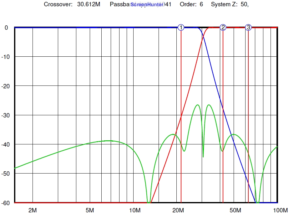
Simulation vs. real world
Diplexer looks good!
Why diplexer? The diplexer directs the desired signal to the antenna, but harmonics to the dummy load (the so called harmonic load). In the LDMOS amplifier (push-pull), the third harmonic can be only 10-12 dB weaker than the useful signal, This means if you drive 1.5 kW antenna, and 150 W go to dummy load!
20 m Diplexer
More diplexers....
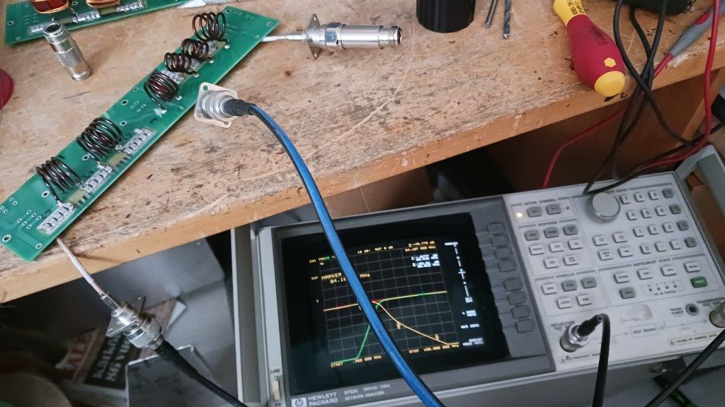
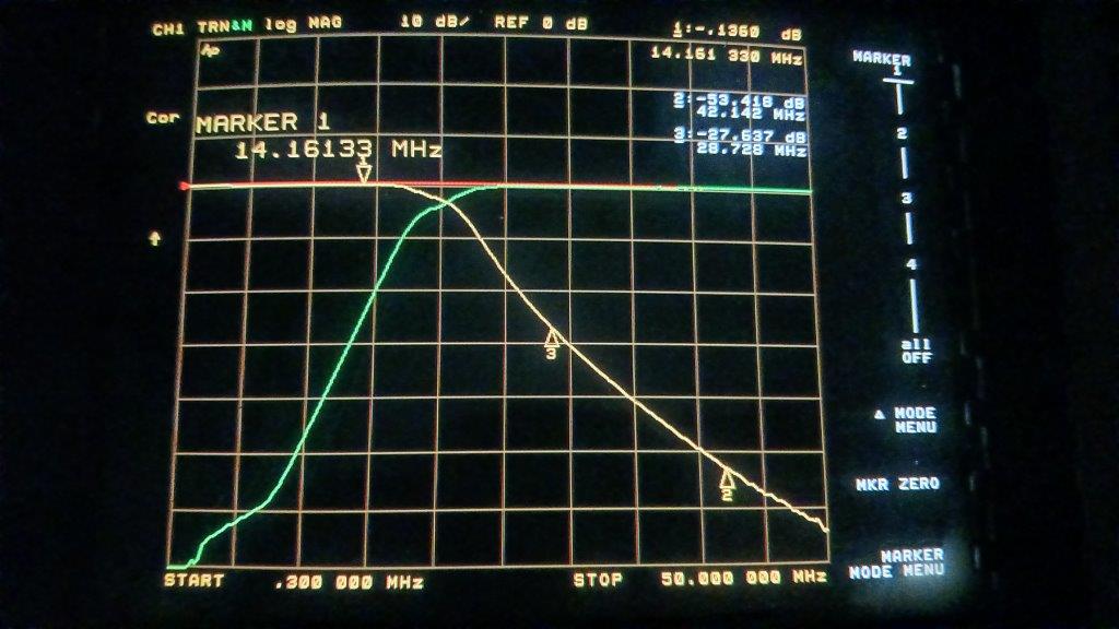
Testing a diplexer with network analyzer
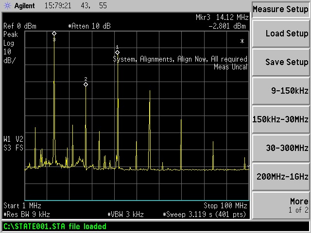
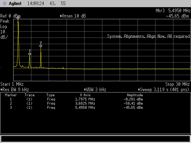
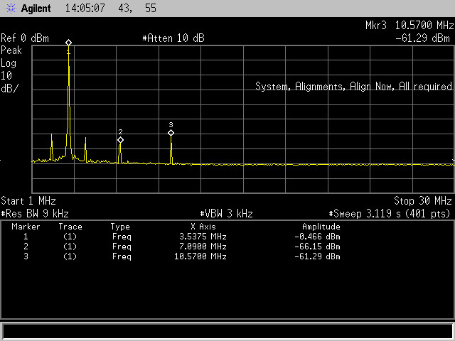
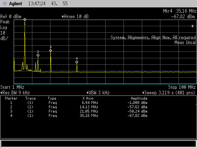
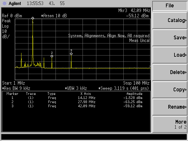
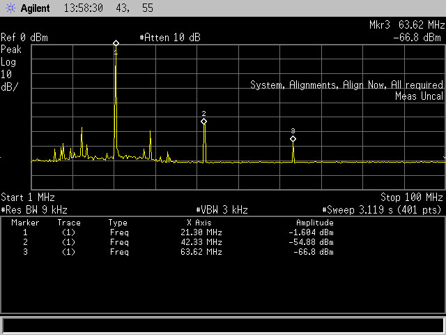
Output without diplexer
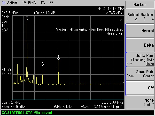
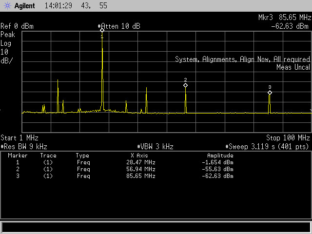
With diplexer.... 3rd harmonic -50 dB@ 2 kW...
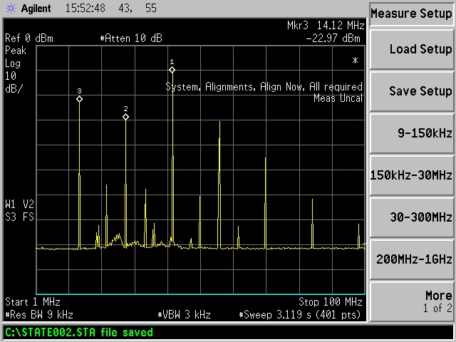
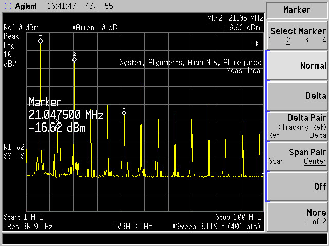
Dummy load spectrum
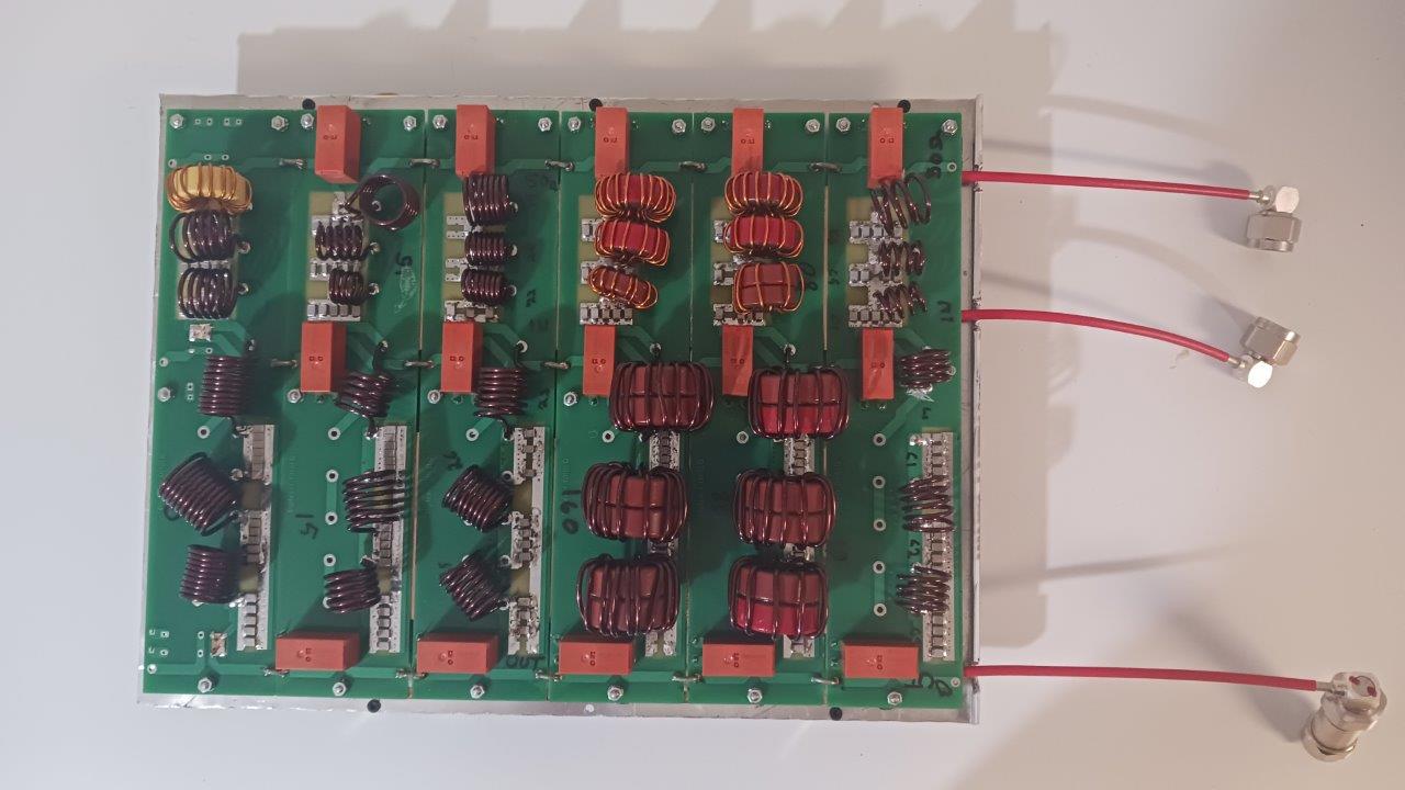
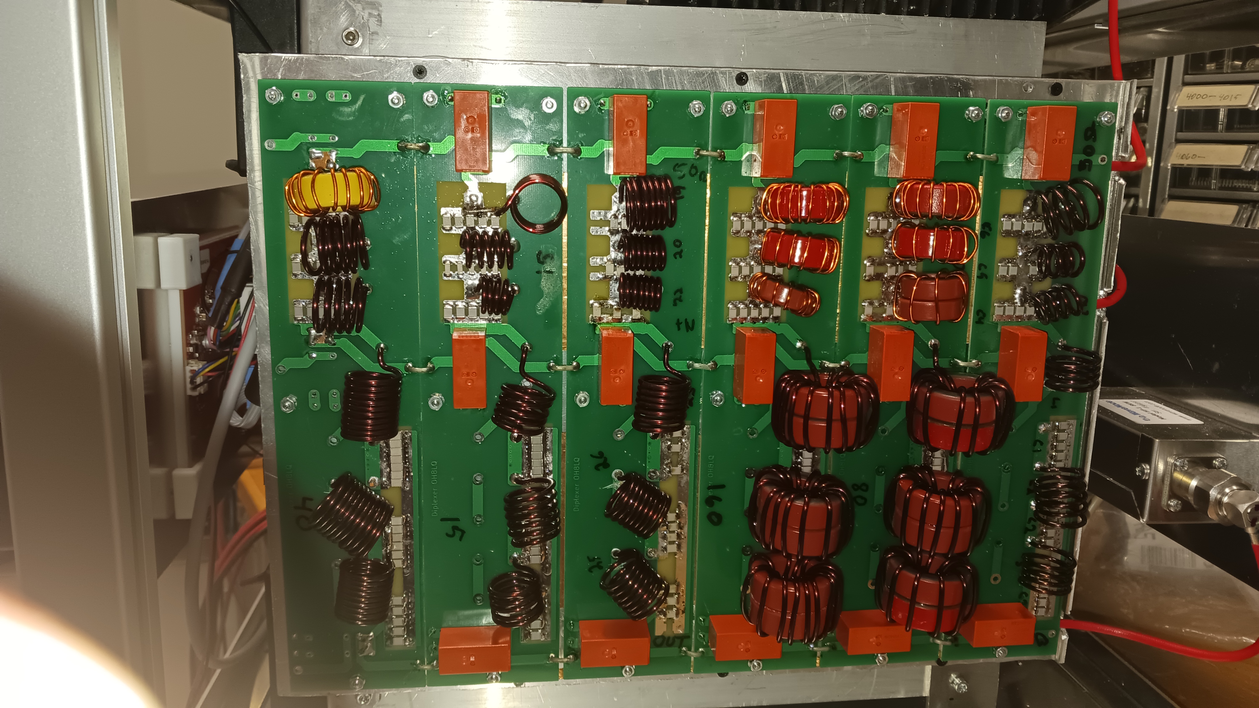
- Modular Architecture: The printed circuit board is partitioned vertically into six distinct filter blocks, with each section dedicated to a specific amateur radio band ranging from 160 meters down to 10 meters (WARC including).
- Filtering Methodology: Unlike a standard low-pass filter (LPF) that reflects out-of-band energy back to the source, this diplexer network topology integrates parallel low-pass and high-pass pathways. The fundamental carrier frequency passes cleanly to the antenna, while the unwanted harmonic energy is diverted into an isolated load.
High-Power Component Selection
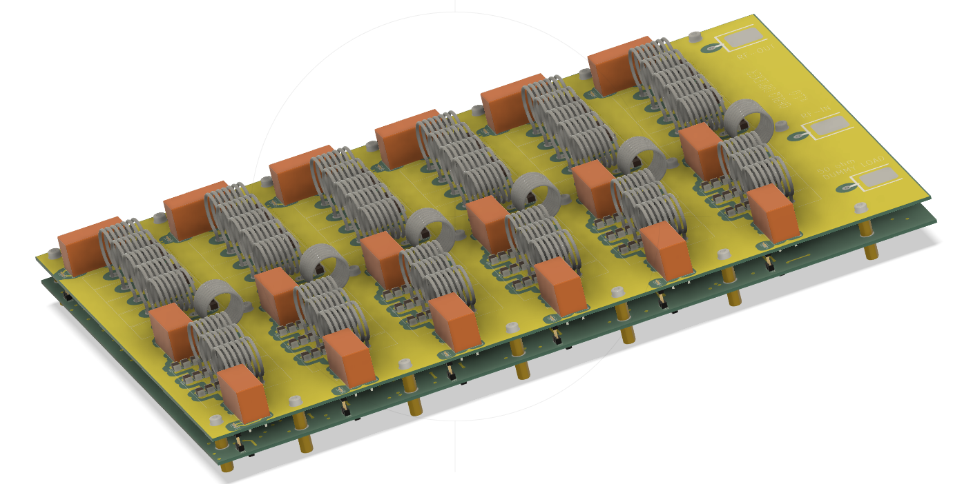
- Toroidal Inductors (Air-Core and Ferrite): The wire gauge is critical to handling up to 3 kW of throughput power without core saturation or thermal runaway.
- High-Voltage RF Capacitors : The Capasitors are positioned across the top and bottom of the board are specialized, high-voltage multi-layer ceramic or mica capacitors (such as ATC or equivalent). They are engineered to endure high reactive RF currents and steep voltage peaks without dielectric breakdown.
RF Interconnections & Coaxial Leads
- Three heavy-duty, Teflon-insulated coaxial lines terminate on the right margin of the board, outfitted with high-power RF connectors:
- RF Input: Carries the raw, unfiltered combined RF power straight from the amplifier's pallet combiner network.
- RF Output: Delivers the pure, filtered fundamental carrier frequency toward the output T/R relay and the rear panel antenna port.
- Harmonic Load Output: Routes the separated out-of-band harmonic spikes into an independent, fan-cooled dummy load where the waste energy is safely dissipated as heat.
Test at 1,5 kW per band
160 m
80m
40 m without filter and with filter
20 m
15 m
10 m
Need more attenuation for 3rd harmonics at low band.
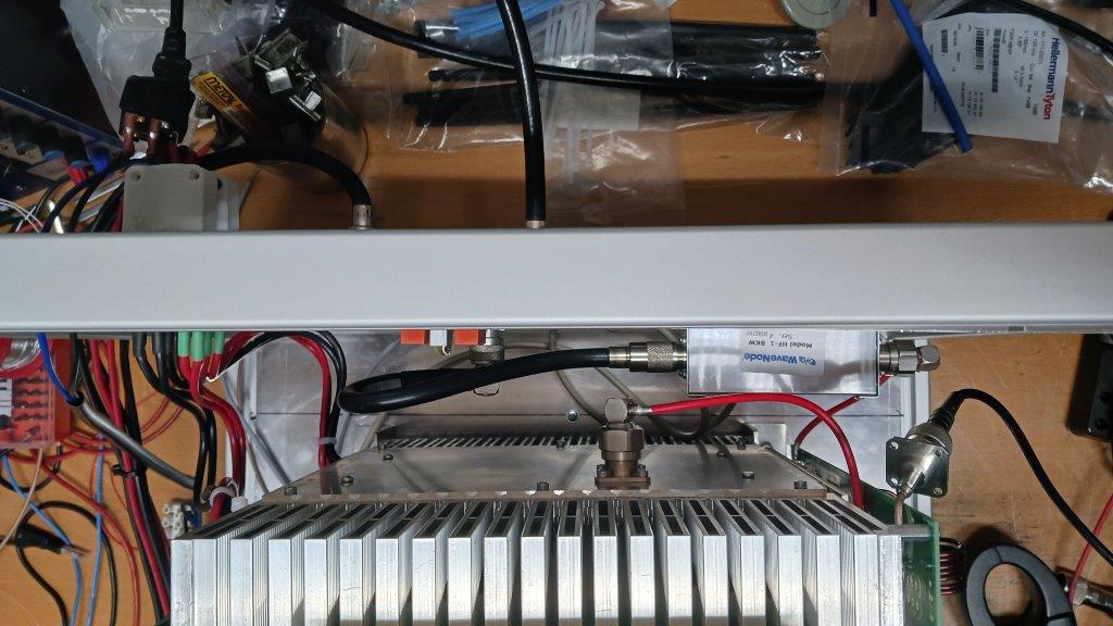
WaveNode SWR sensor added inside of amplifier
Installed Diplexers
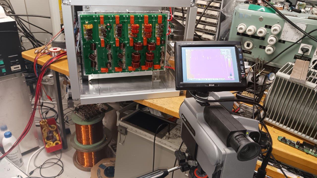
Thermal cam tests
Diplexer and harmonic load
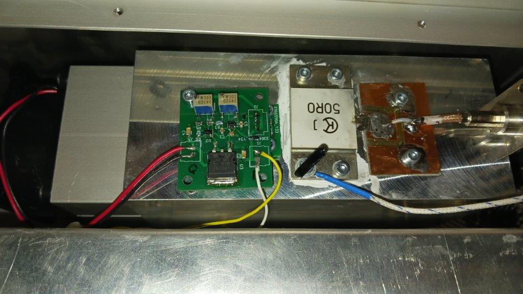
Harmonic load with FAN-control
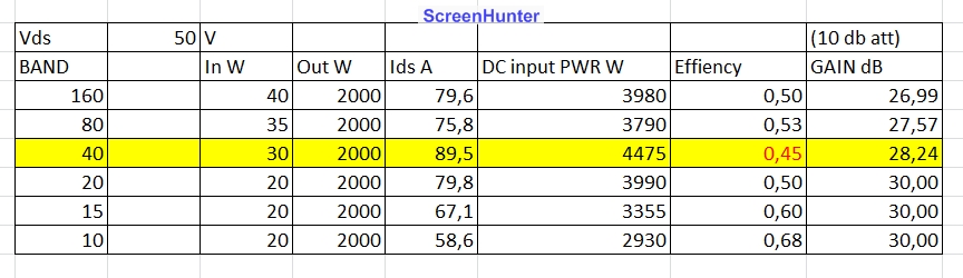
Effiency (at first test)
Arduino controller on board
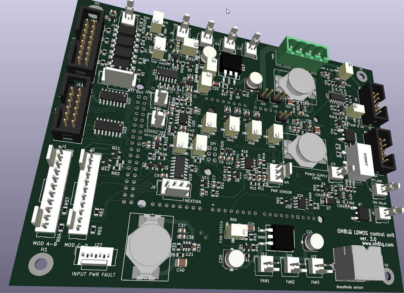
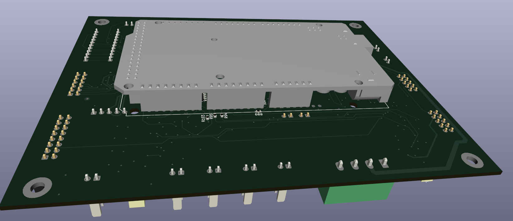
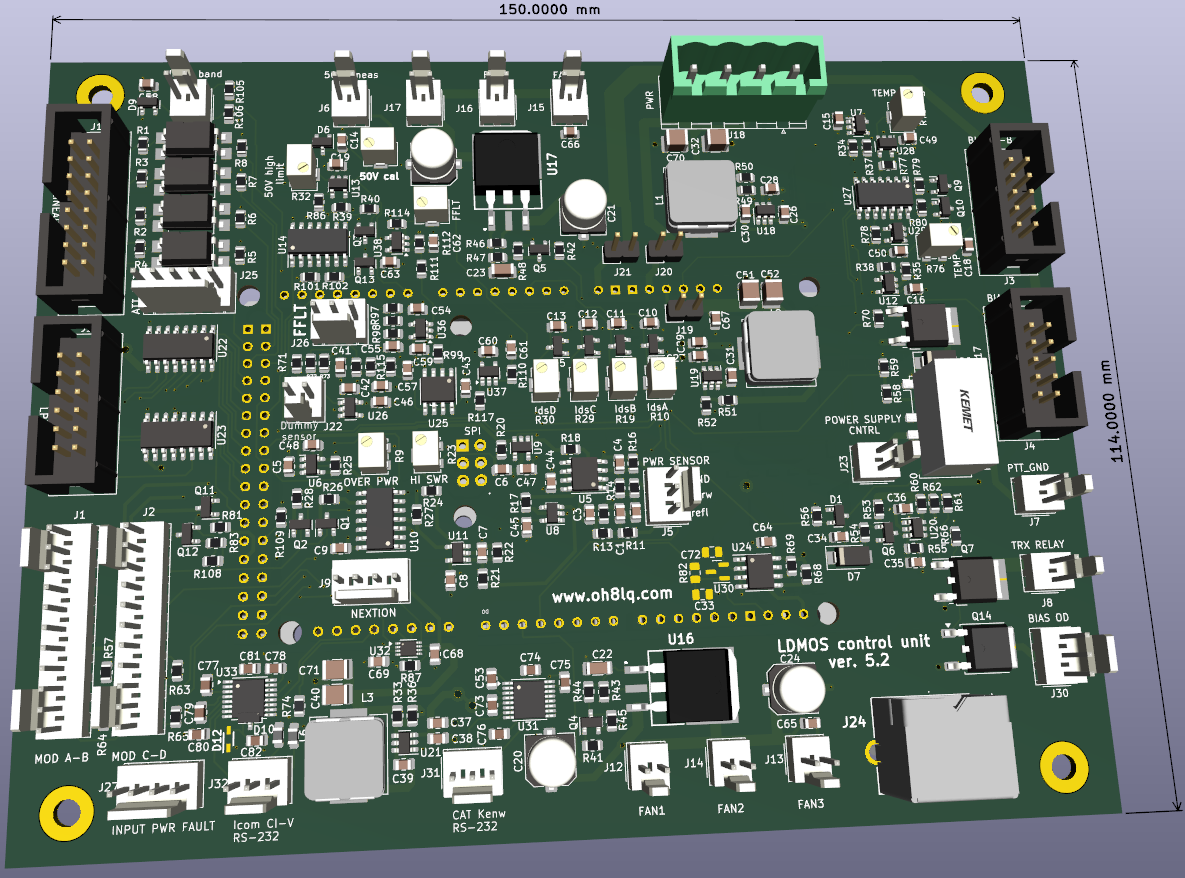
Board works with Arduino DUE and Giga WiFi. Board with
Giga is in future remote controlled...
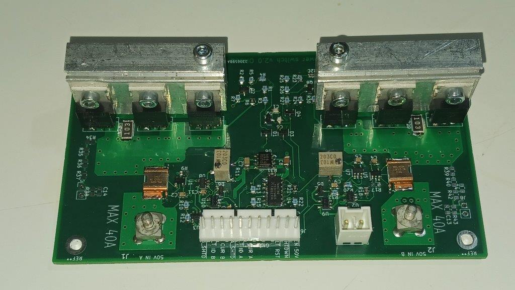
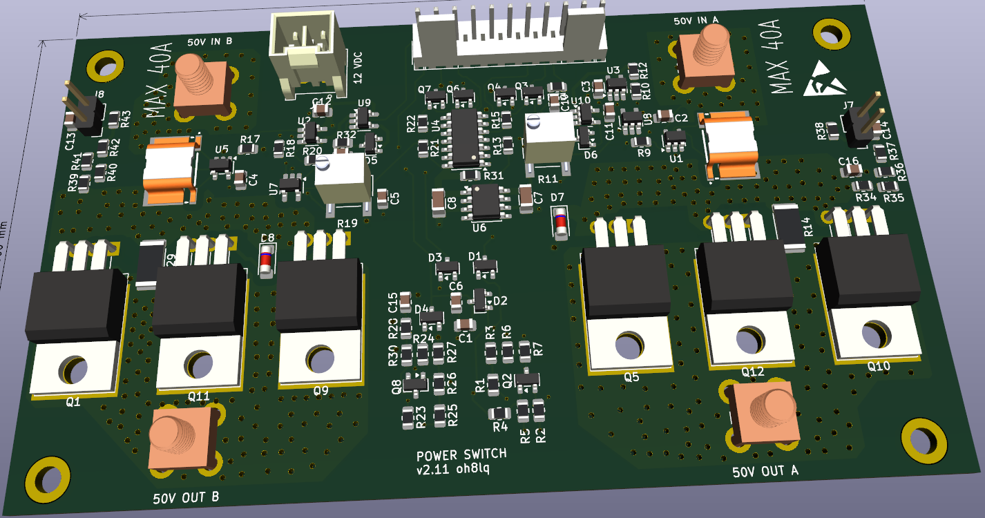
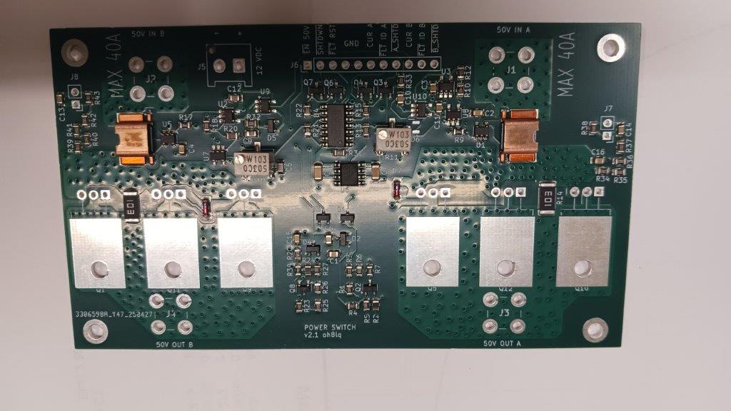
I have some pcs. SMD ready assembled PCB´s. Ask!
Price 48.00 EUR + shipping
TRX-relay board
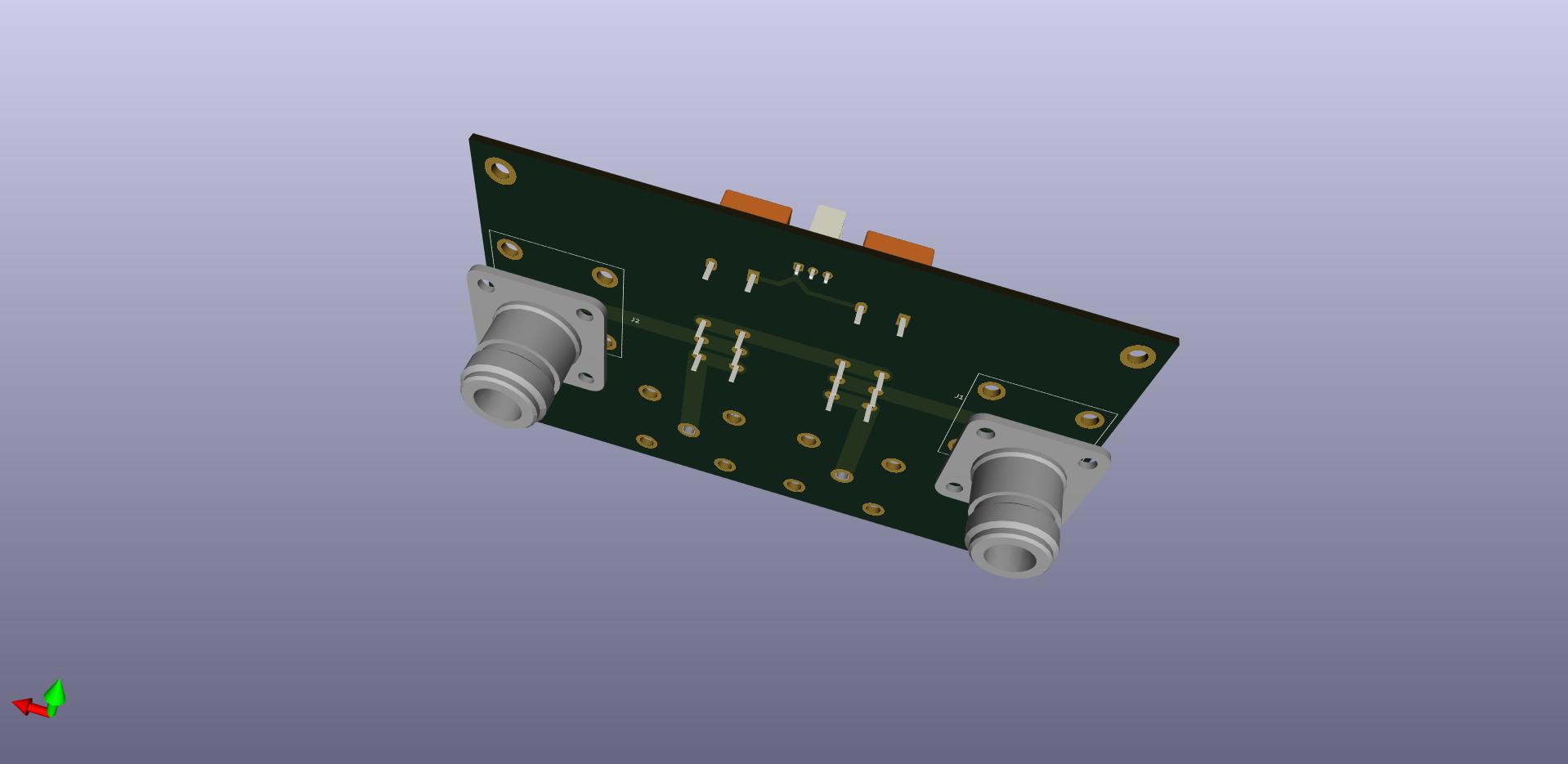
Input step attenuator
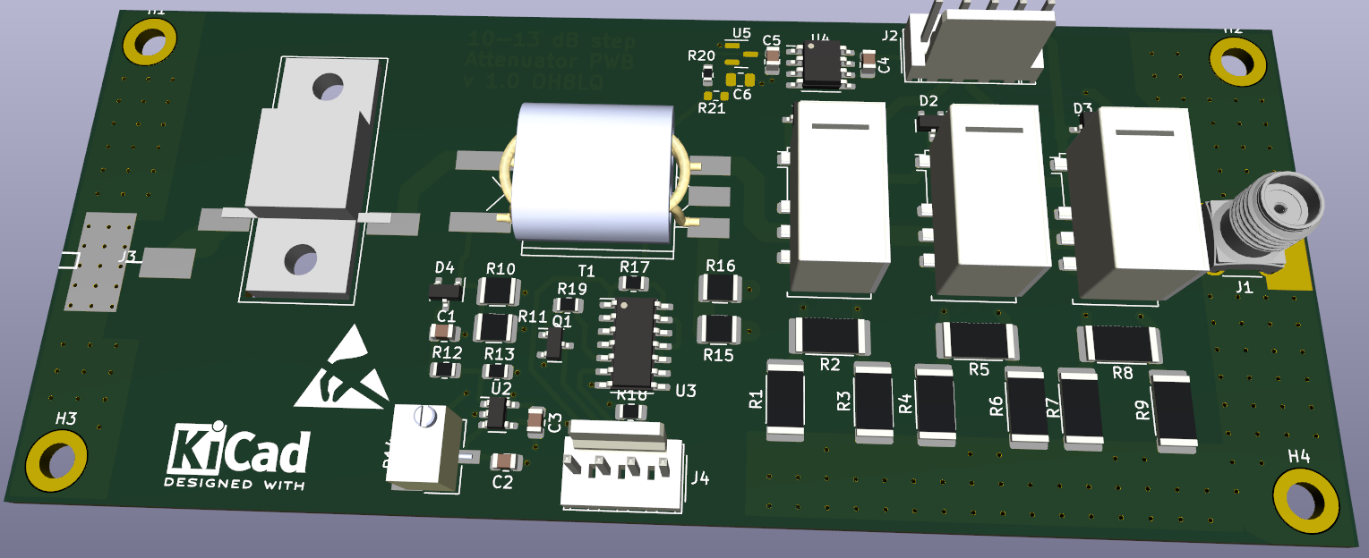
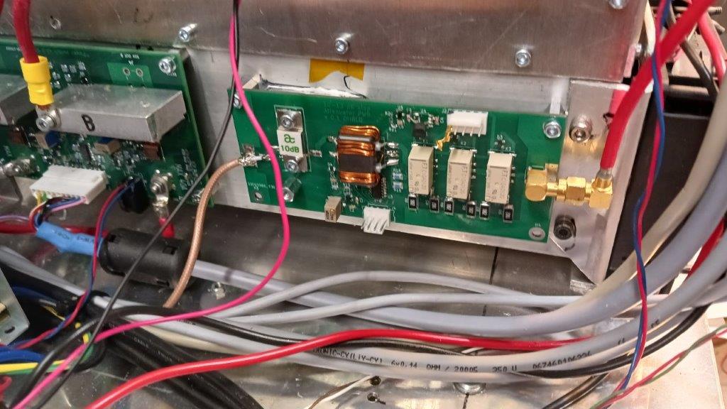
Input Attenuator and over drive detection
FAN speed controllel with LM35-sensor
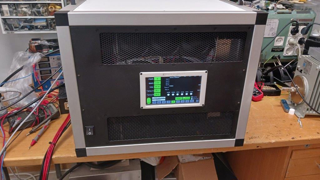
Almost ready to use
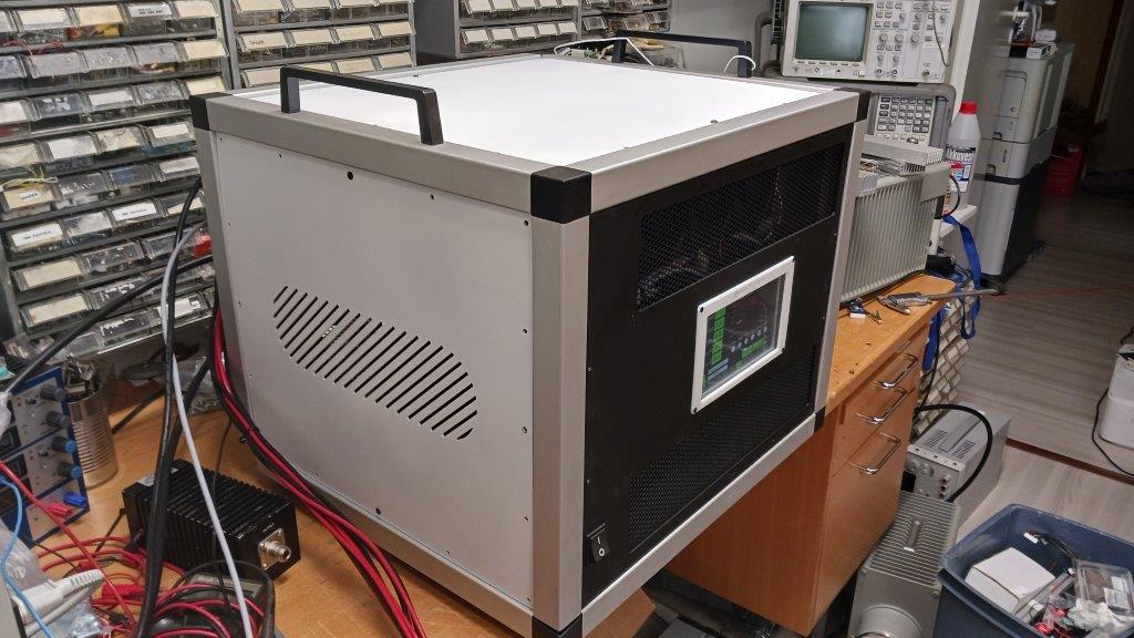
Added handles, weights approx. 30 kg
The amplifier was in real operation for the first time at the WPX CW 2023 contest. No problems found.
TFT-touchscreen UI first version
version (5.10.2024)
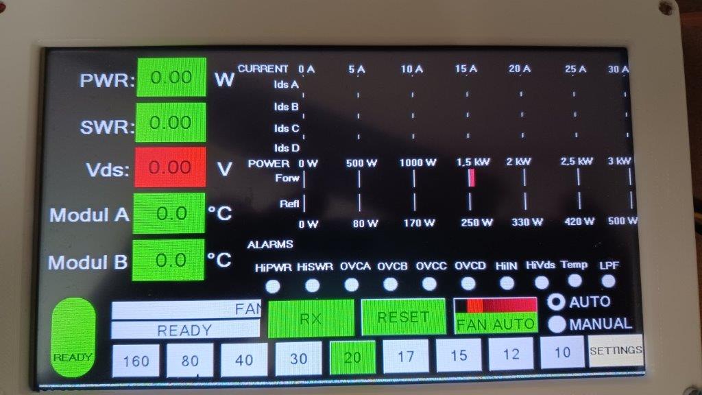
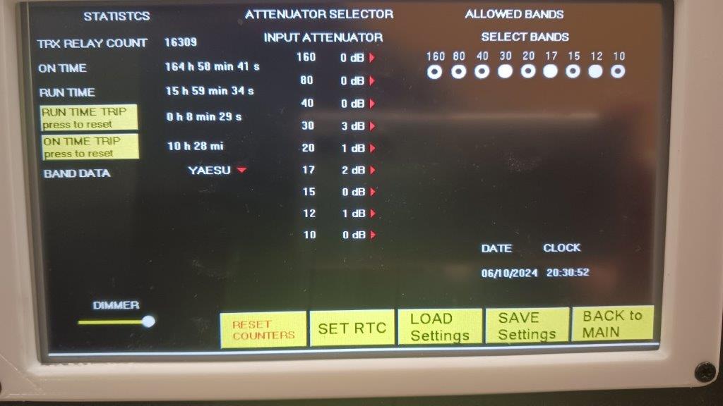
Early version UI
UI is under continuous development!
The goal is to have a version suitable for remote use at some point,
but the original design does not support it.
Look latest version Nextion LDMOS amplifier GUI
First remote GUI
Three phase power with ESP120
9 kW 50 V three-phase power supply ESP120
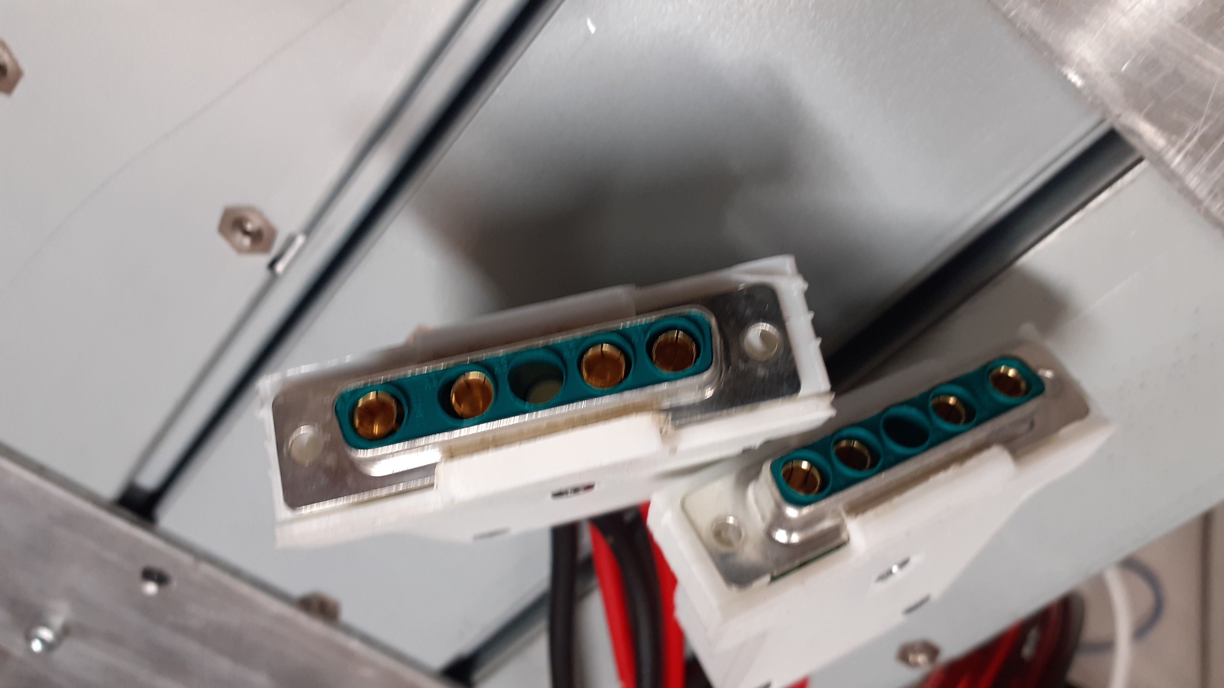
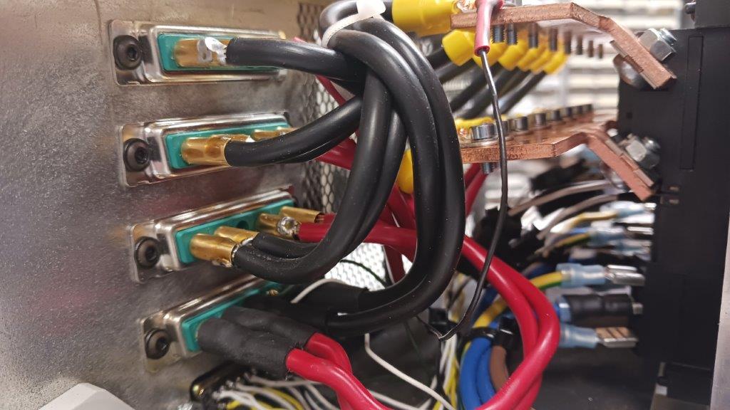
Power connectors
Three phase power supply with Huawei
Three-phase power supply from three Huawei R4850G2 power supplies connected in parallel. Maximum power about 9 kW.Why three power sources when one or two would be enough? In three phase system, loading one phase would cause a so-called bias load to the power grid.
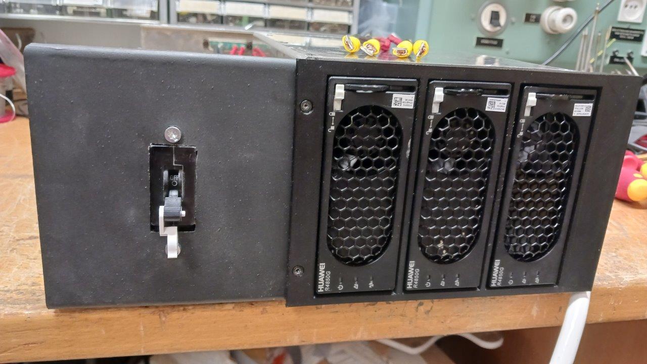
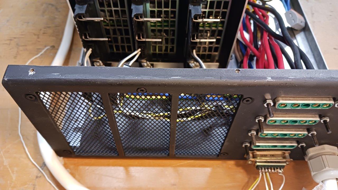
DC output connectors and D15 connector CAN bus for control
Linear + power :)
The large housing underneath is the power of the GU84 tube amplifier.
TO BE CONTINUE....