3 kW linear amplifier with four ART1K6 LDMOS fets
The purpose of the project is to build a linear LDMOS amplifier for HF bands 160-10 m. The amplifier must withstand a continuous power of 1.5 kw, because of reliability, I have ended up using several separate amplifier modules. Implemented with four modules, only less than 400 W of power is taken from one module. It is possible to get a power of more than 1 kw from each module, so the amplifier will not be overloaded in any situation. I have a PCB for the project, if you are interested, ask! Some of the circuit boards have SMDs already mounted.
The amp does not have WARC bands, maybe I will add them in the future? The six-band diplexer may also work on WARC bands!
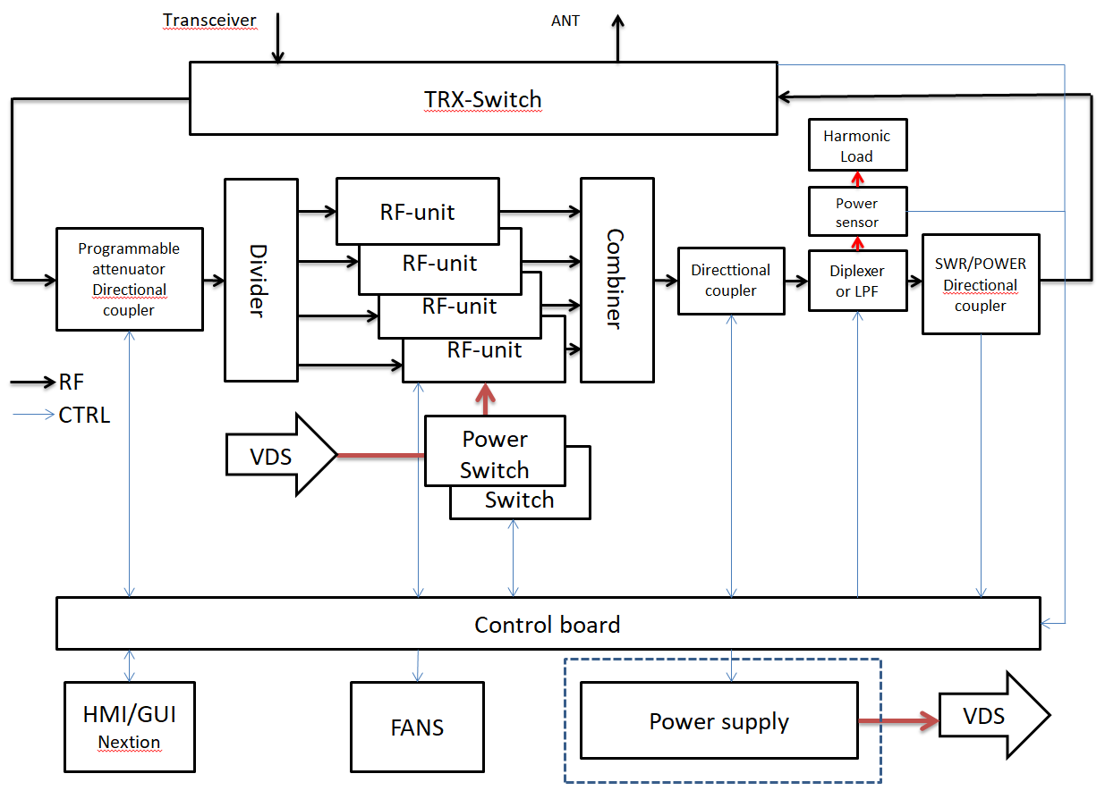
BLOCK DIAGRAM
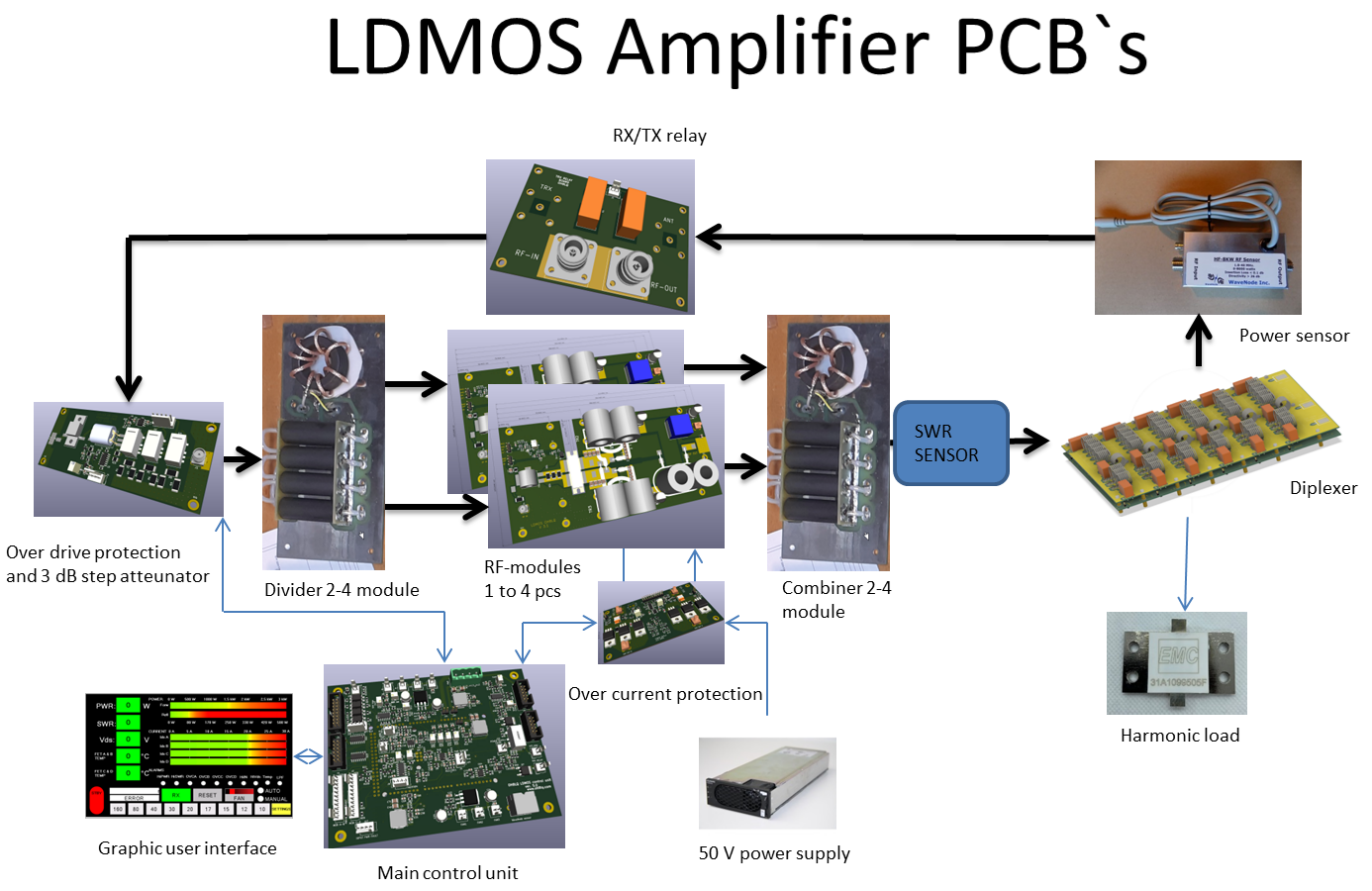
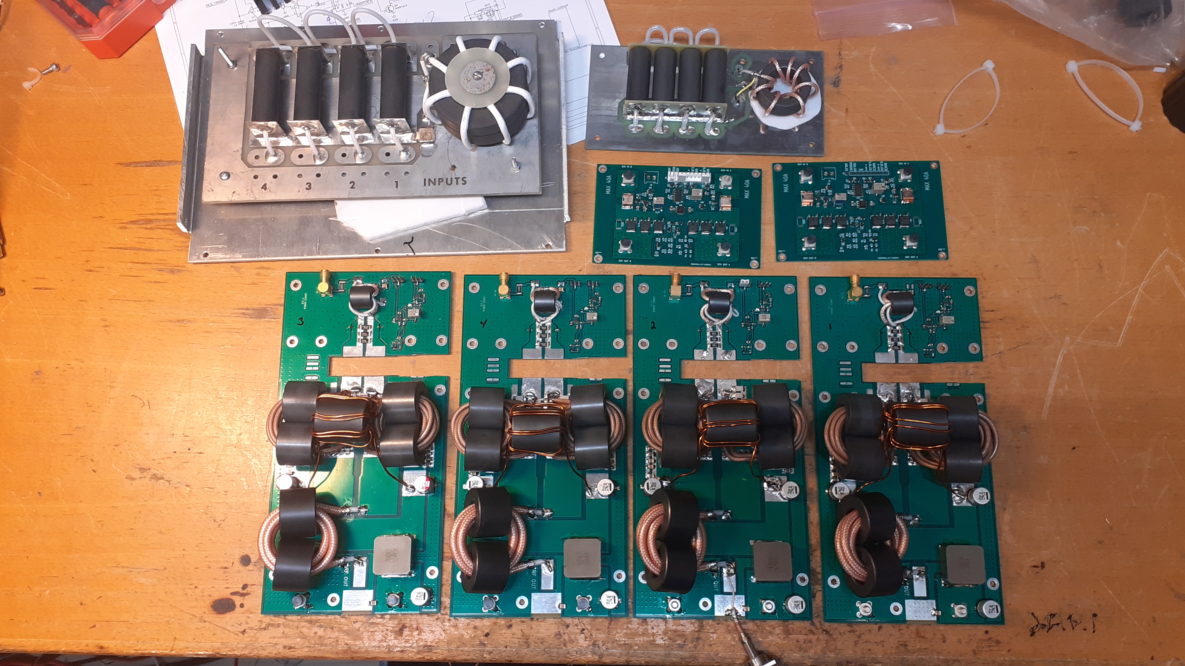
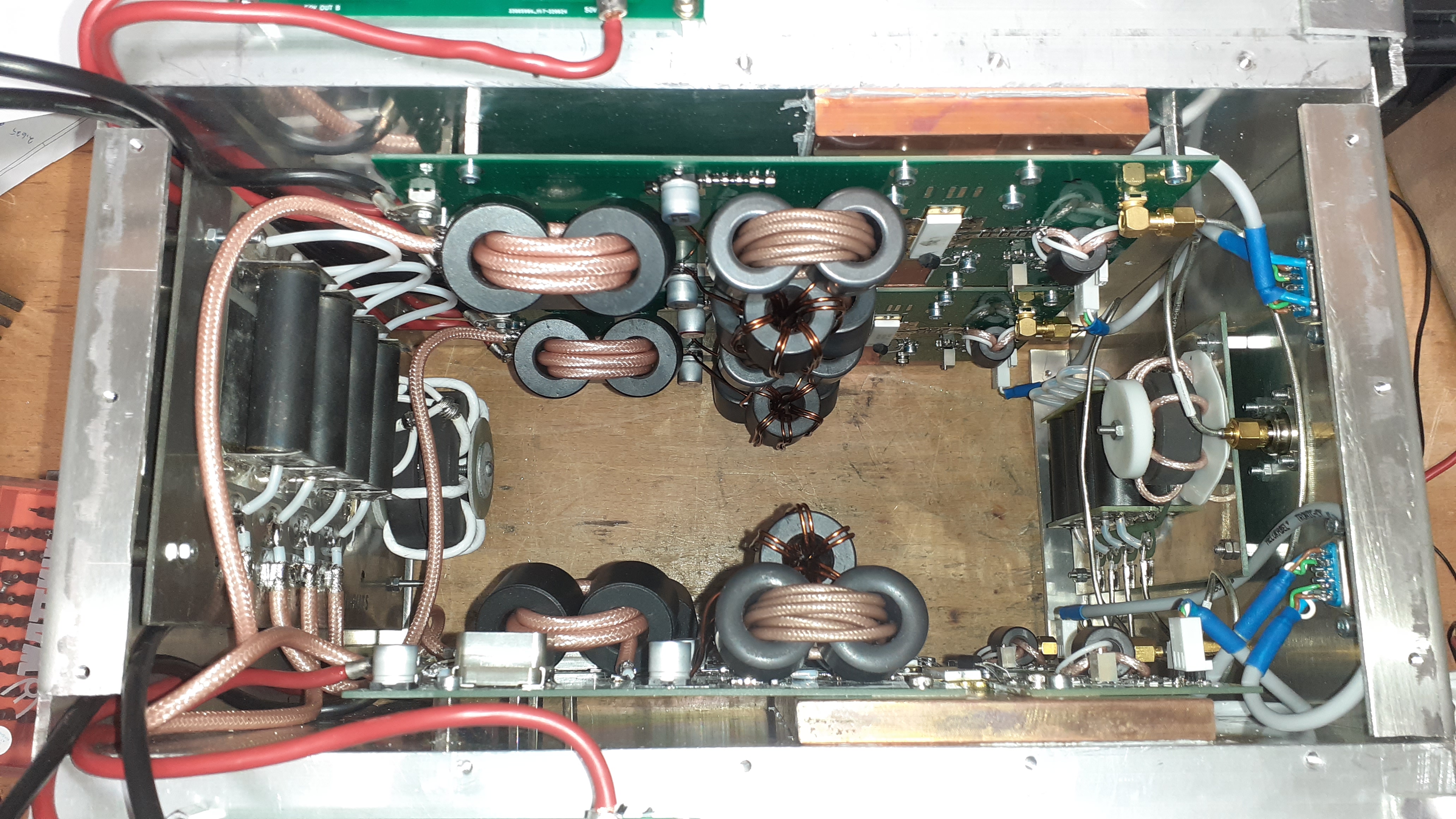
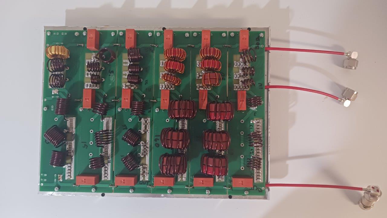
Circuit boards of the RF part
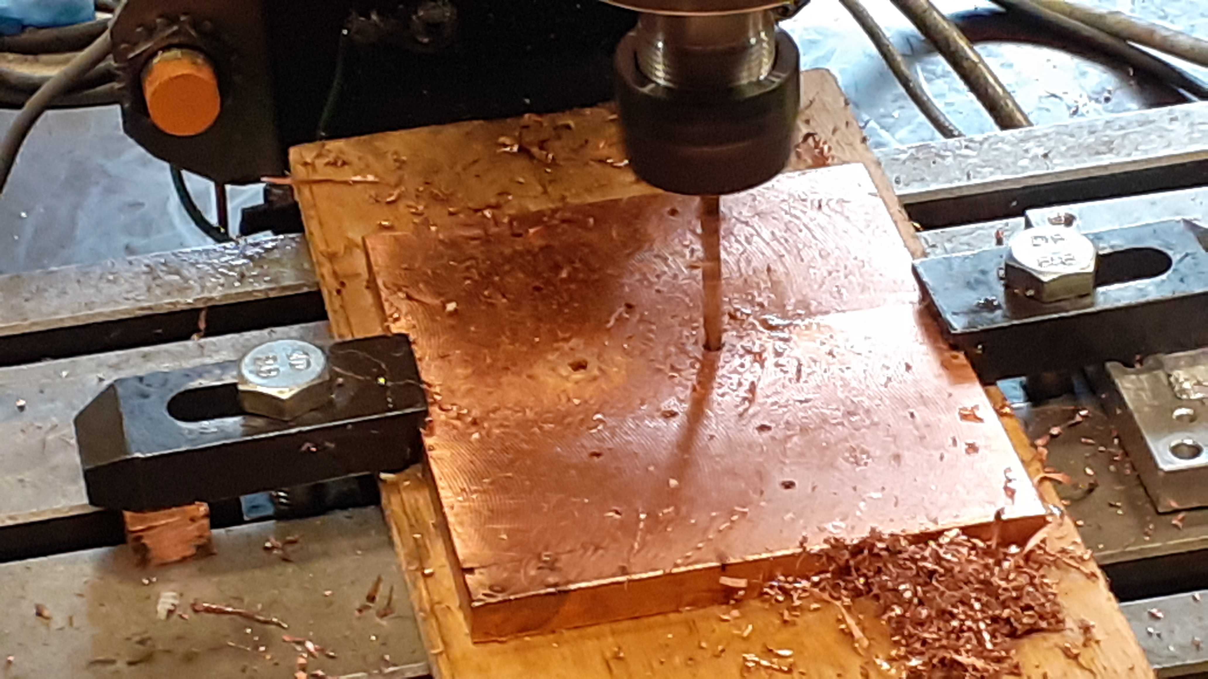
Drilling holes in copper plate
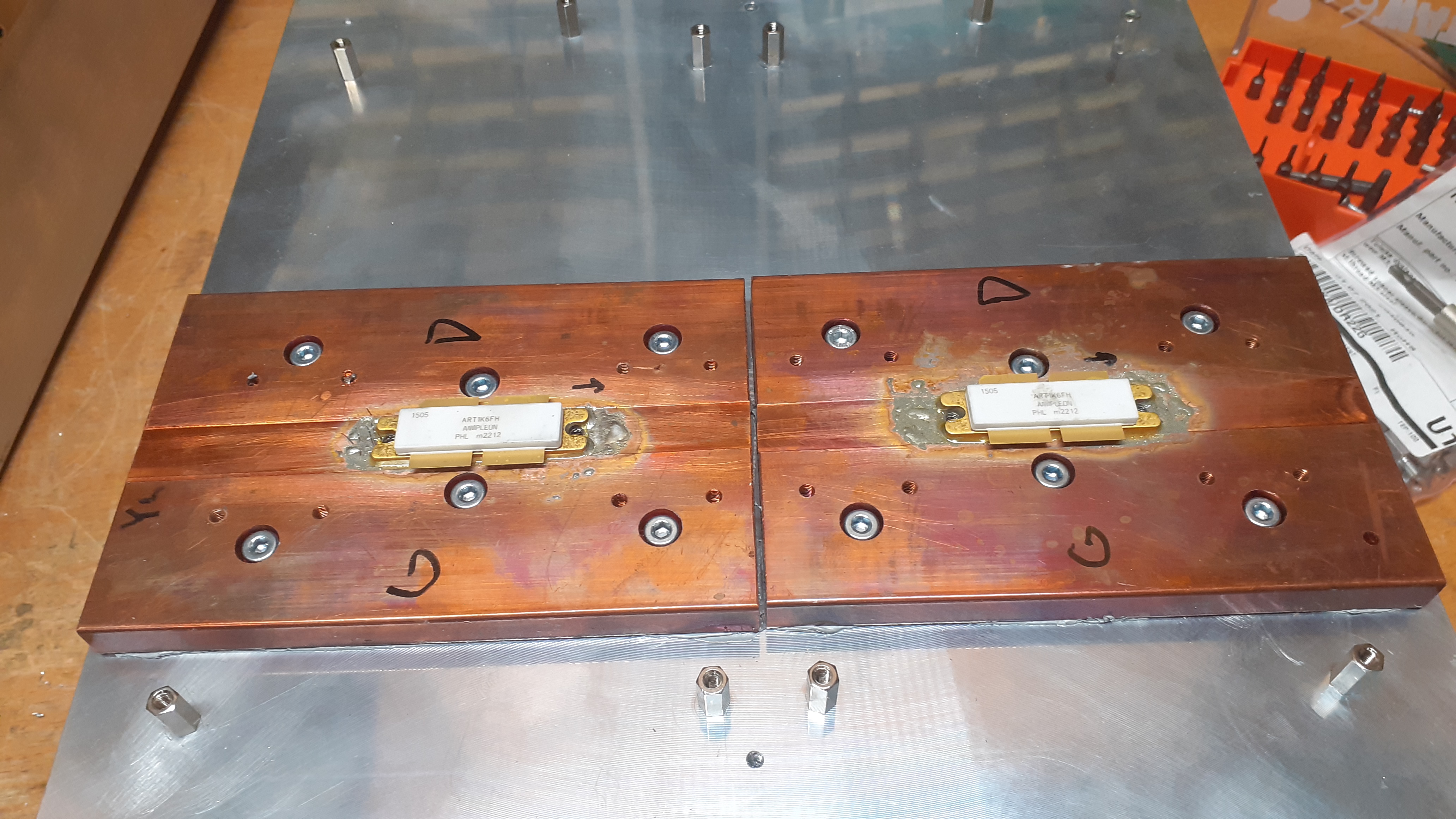
Fets soldered in a cooling plate
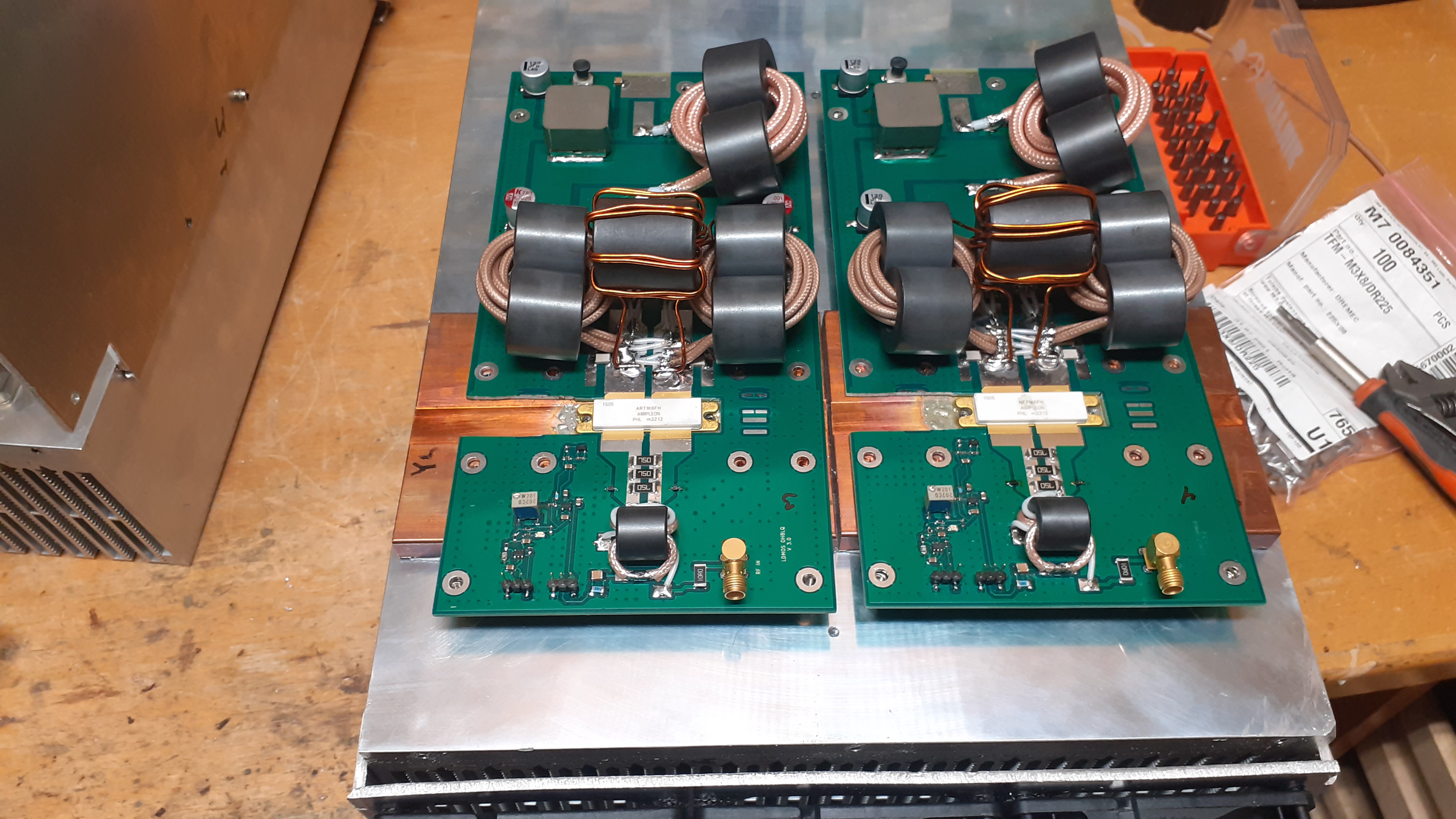
Two RF modules with a heatsink
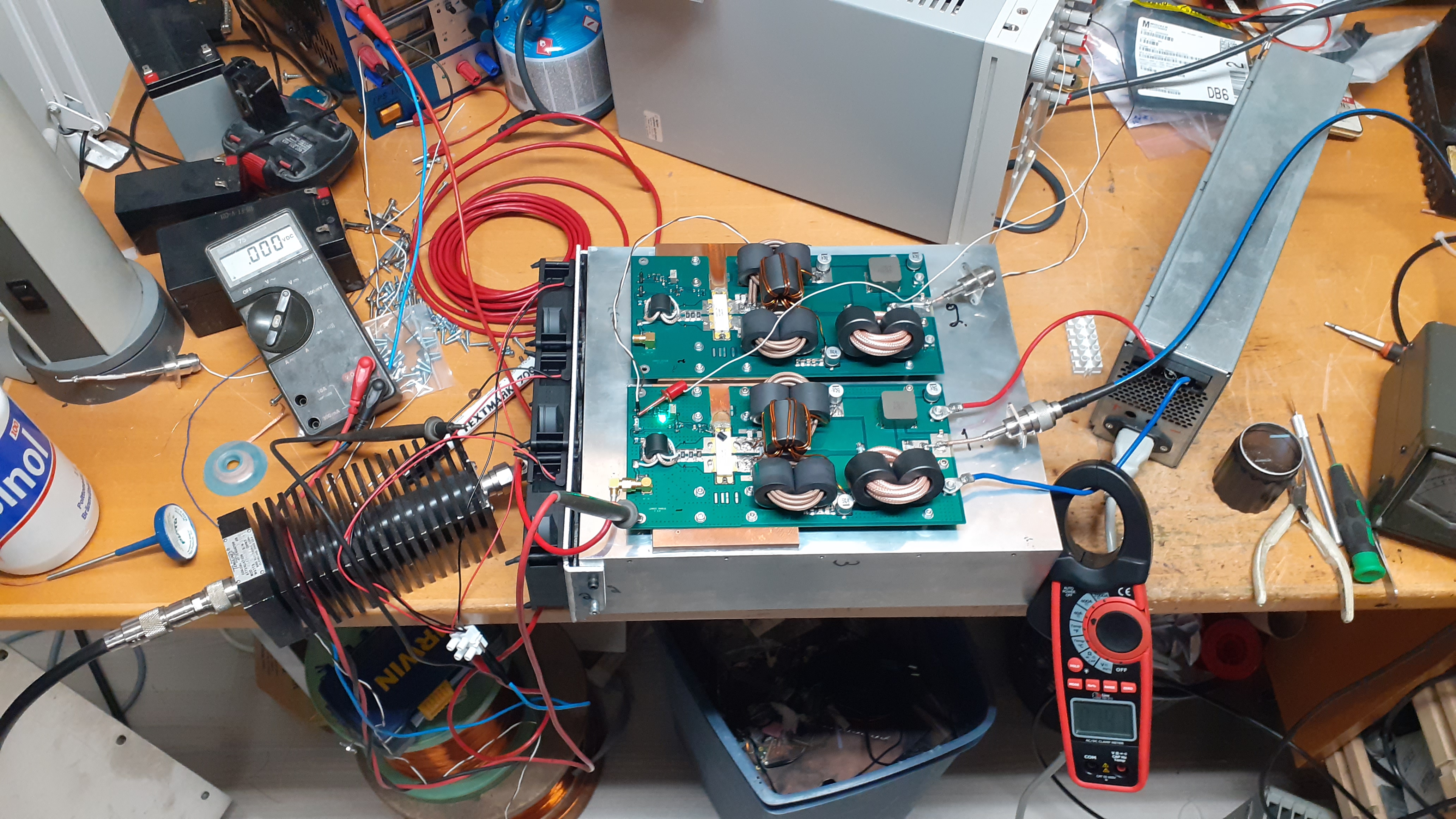
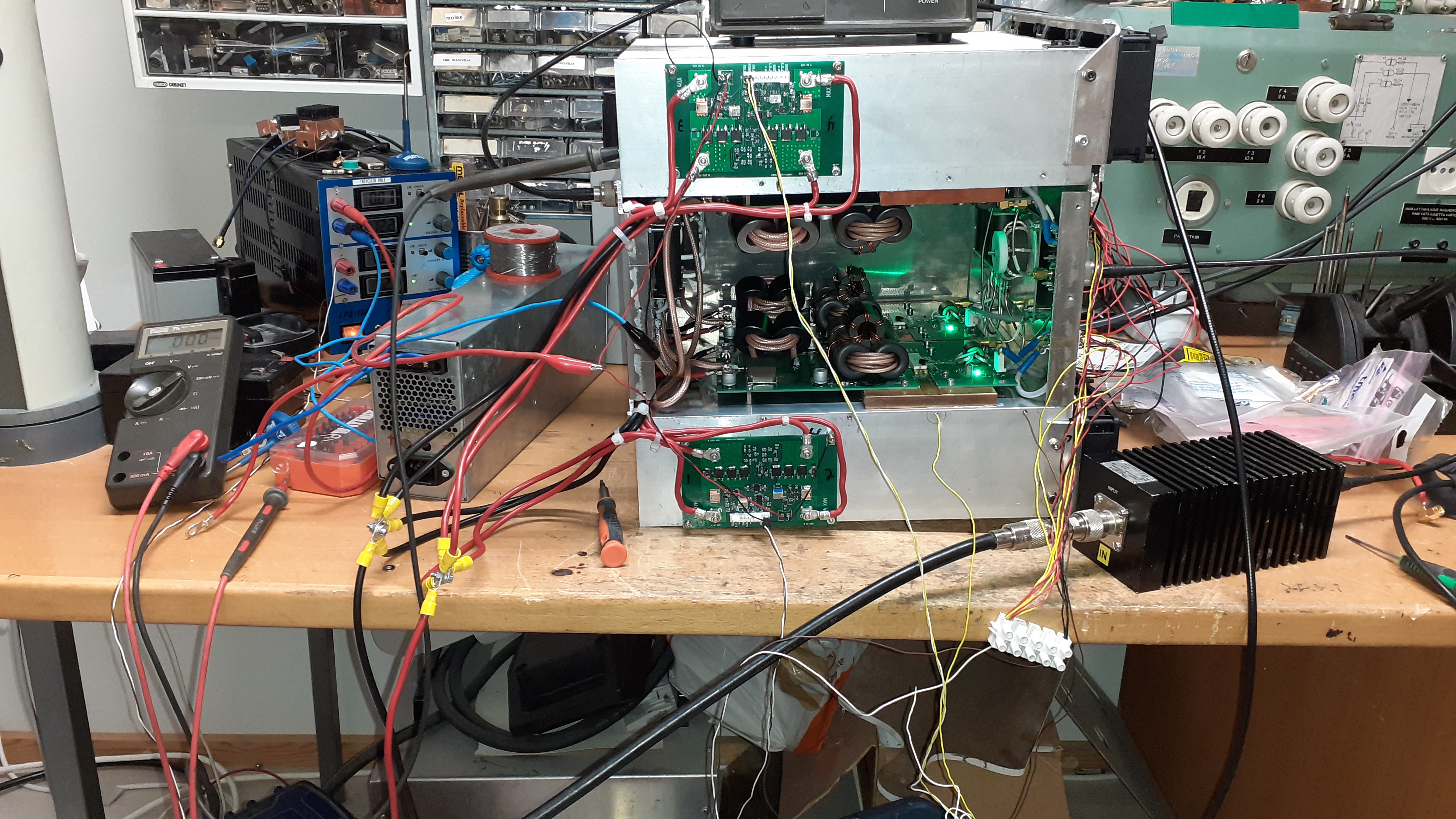
Each module is tested separately

Latest version RF-module
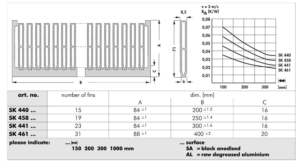
Heat sink datasheet
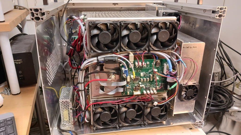
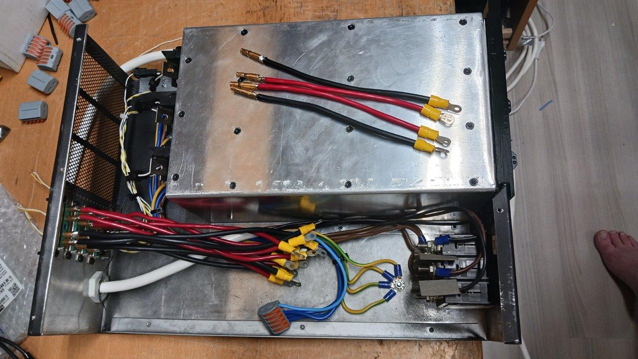
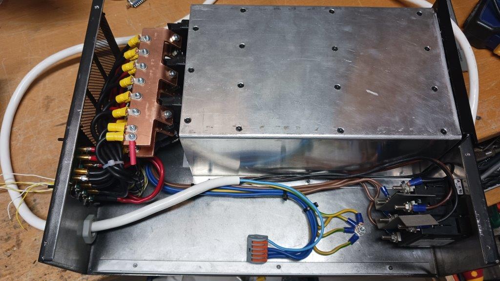
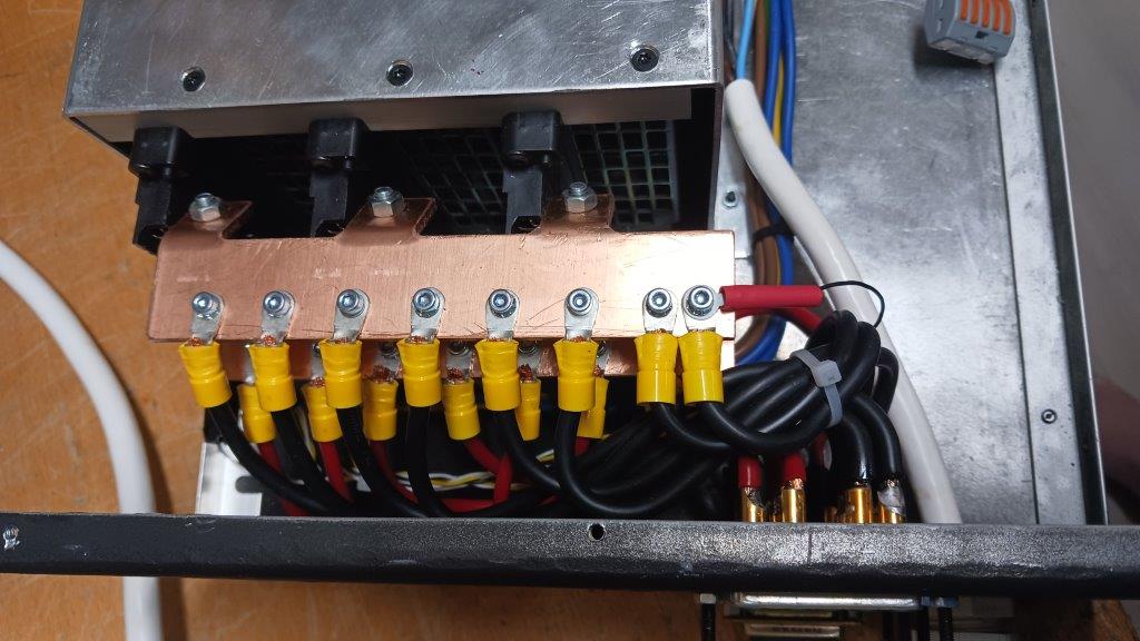
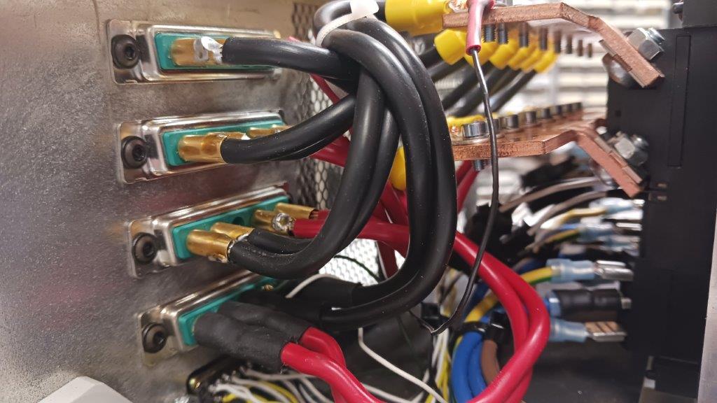
Four modules with heatsink and combiner and divider
RF amplifier unit and power switches
Control board
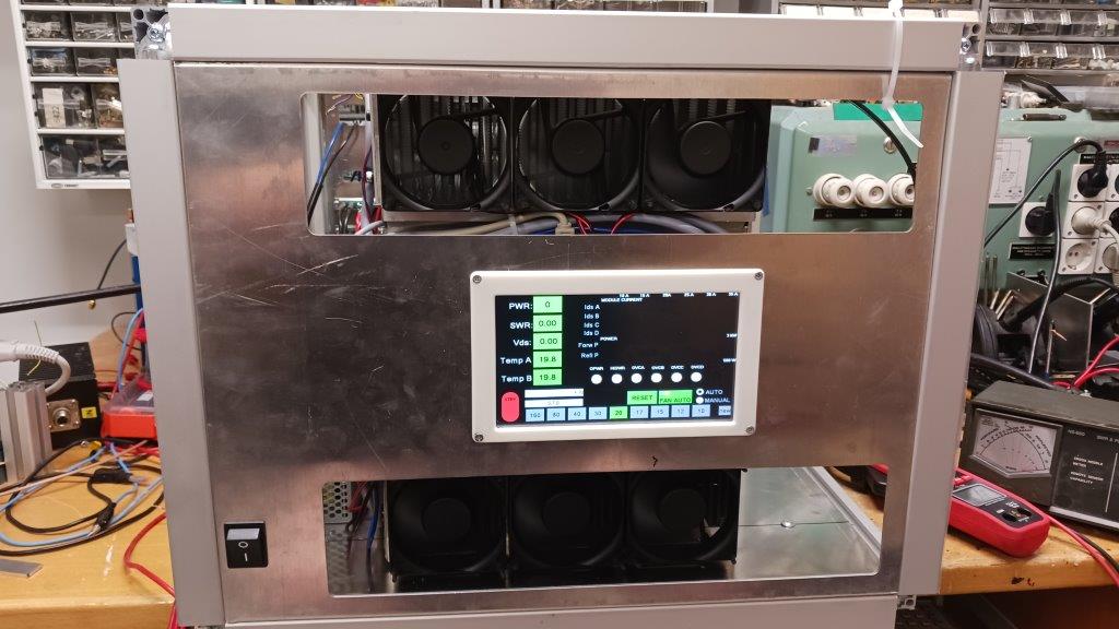
UI at rear panel
DIPLEXERS
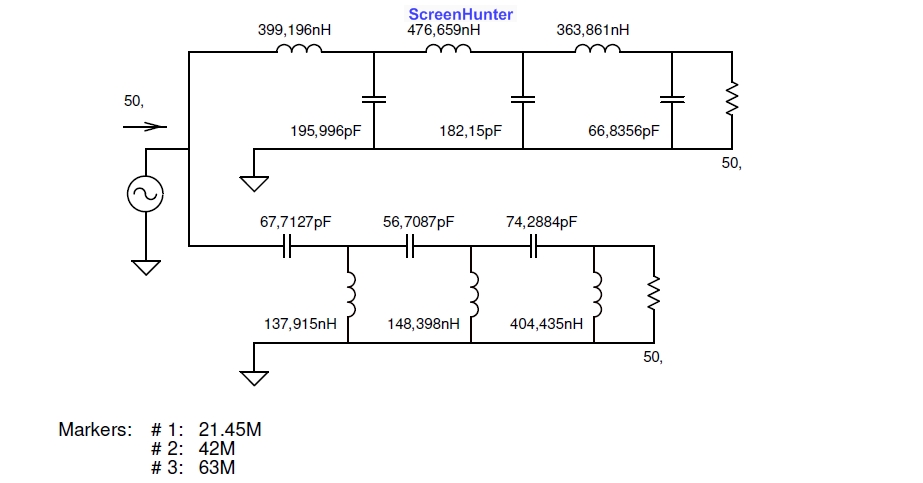
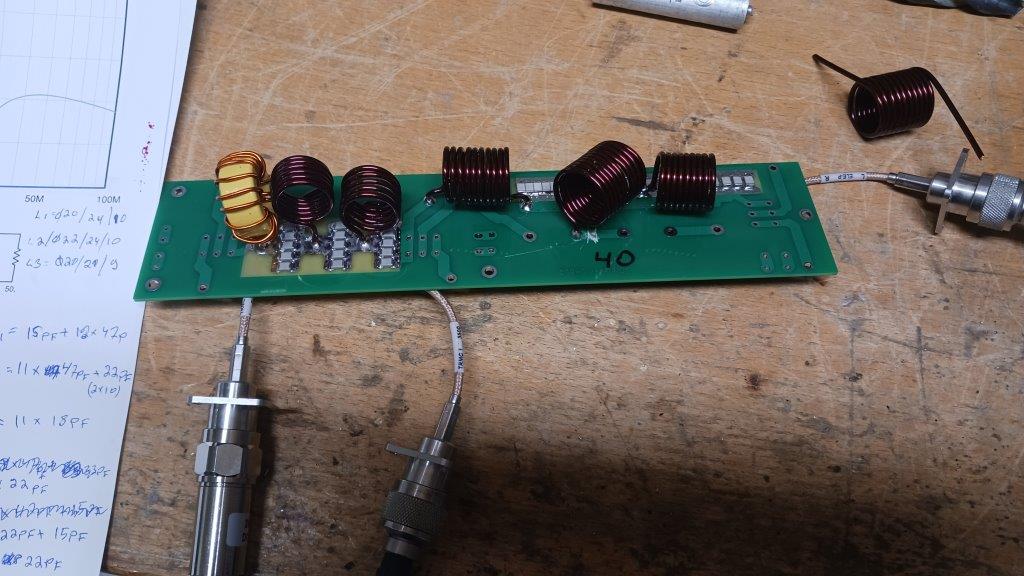
Diplexer calculations: 160 m 80 m 40 m 20 m 15 m 10 m
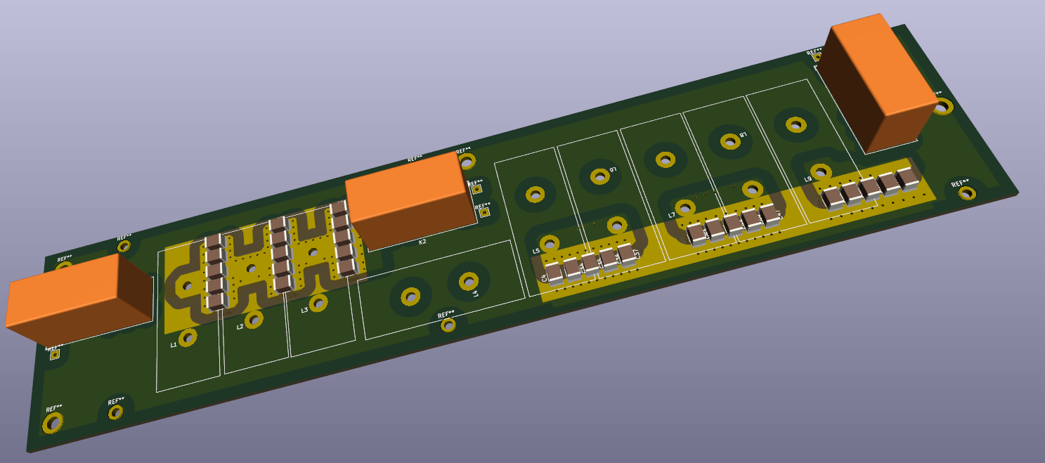
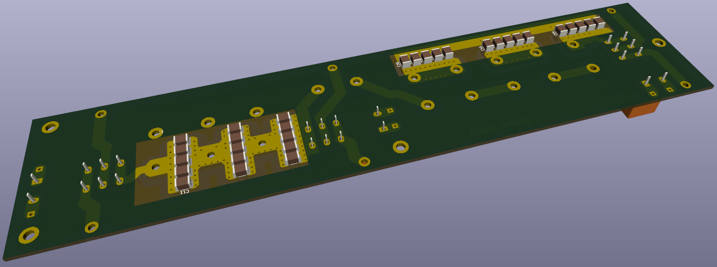
New diplexer board
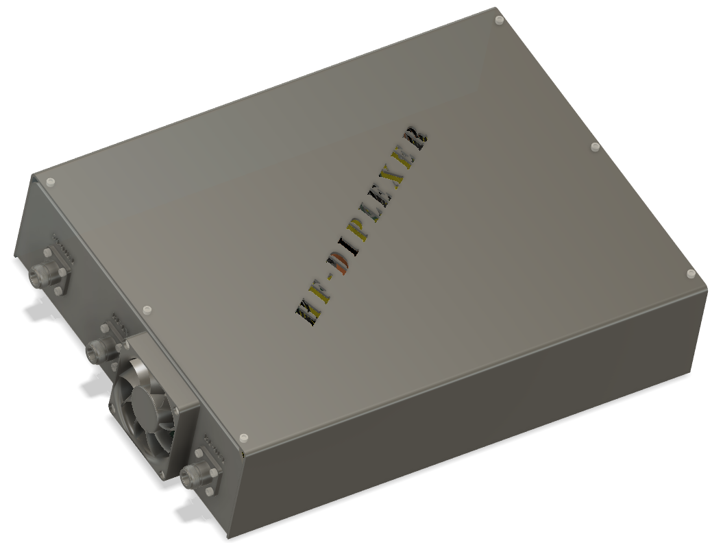
External diplexer box (playing with Fusion360) https://a360.co/44MIS8Y
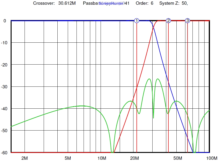
Simulation vs. real world
Diplexer looks good!
Why diplexer? The diplexer directs the desired signal to the antenna, but harmonics to the dummy load (the so called harmonic load). In the LDMOS amplifier (push-pull), the third harmonic can be only 10-12 dB weaker than the useful signal, This means if you drive 1.5 kW antenna, and 150 W go to dummy load!
20 m Diplexer
More diplexers....
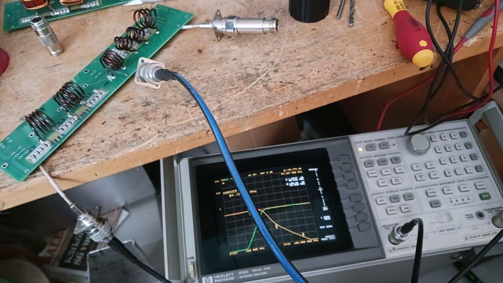
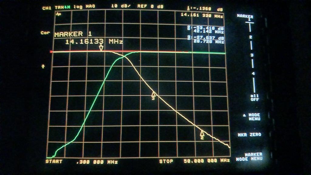
Testing a diplexer with network analyzer
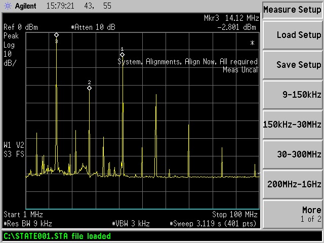
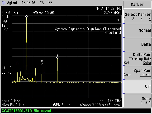
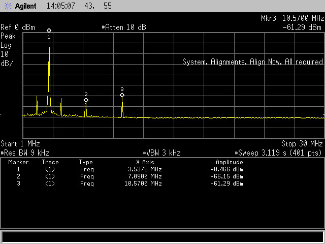
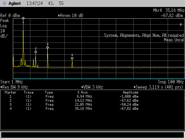
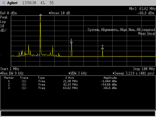
Output without diplexer
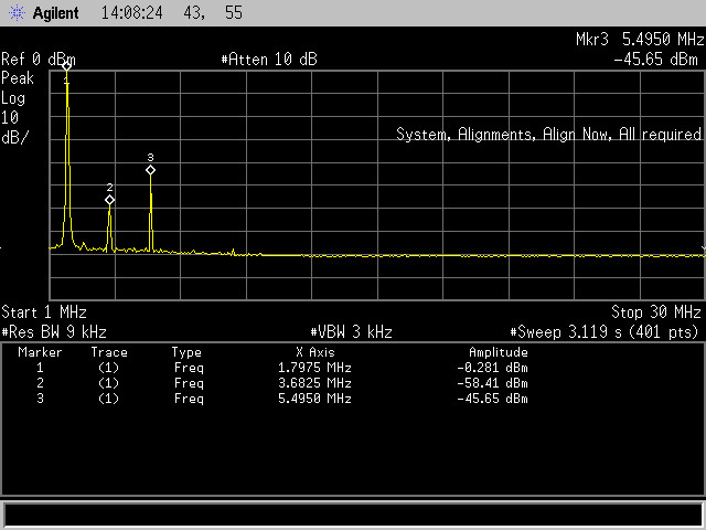
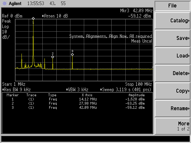
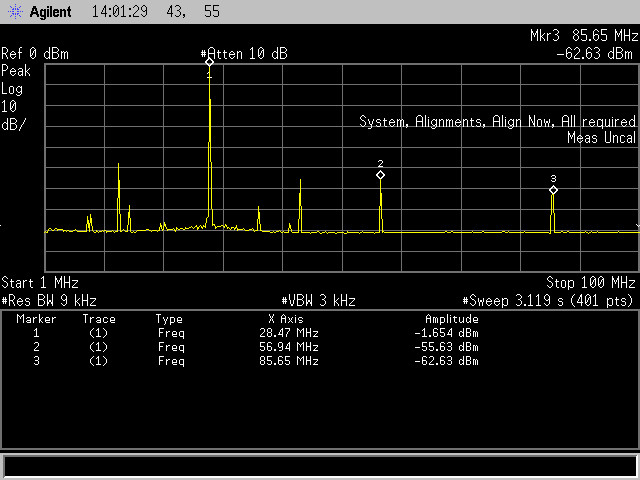
With diplexer.... 3rd harmonic -50 dB@ 2 kW...
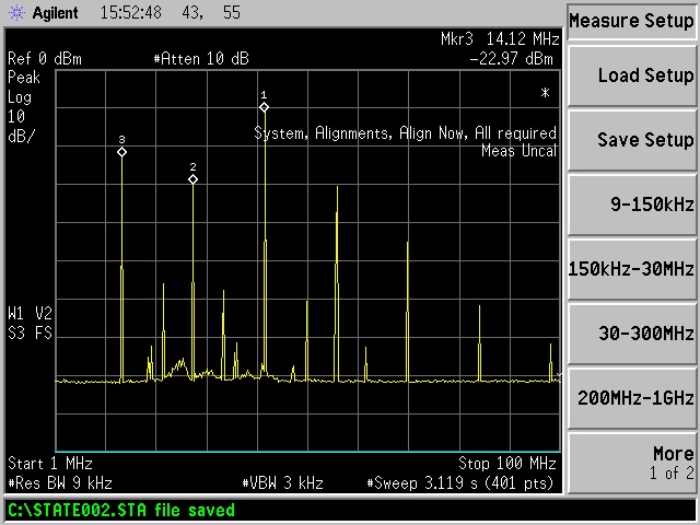
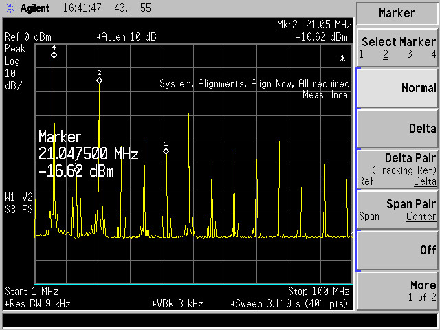
Dummy load spectrum
6-band HF diplexer
Test at 1,5 kW per band
160 m
80m
40 m without filter and with filter
20 m
15 m
10 m
Need more attenuation for 3rd harmonics at low band.
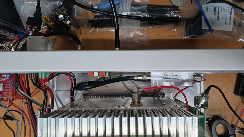
WaveNode SWR sensor added inside of amplifier
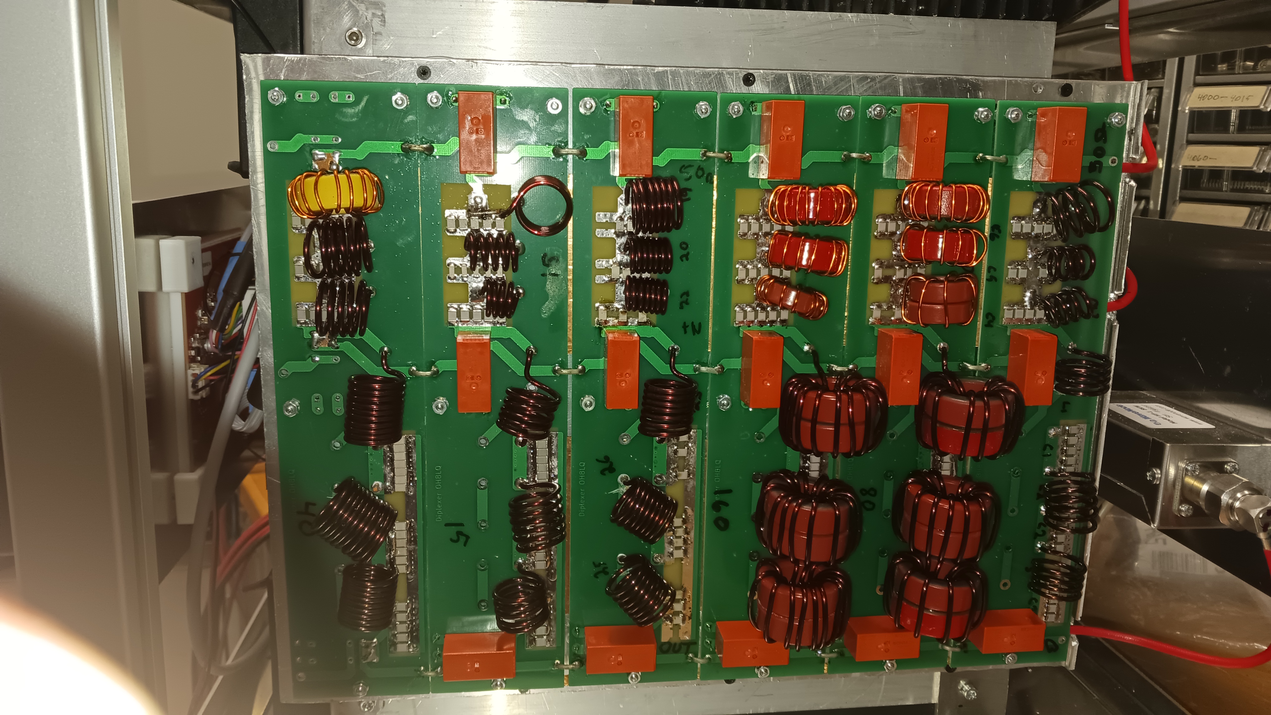
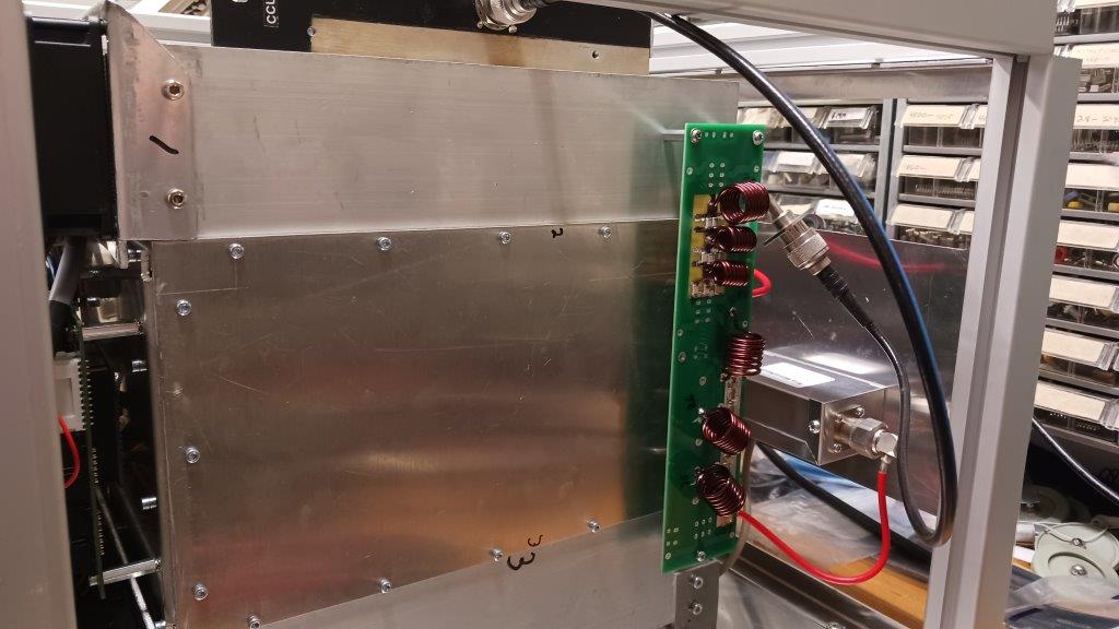
Installed Diplexers
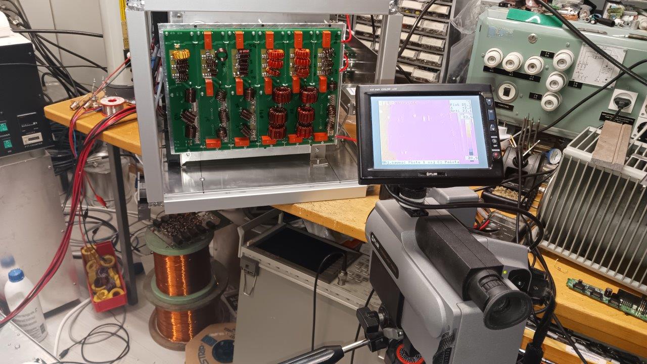
Thermal cam tests
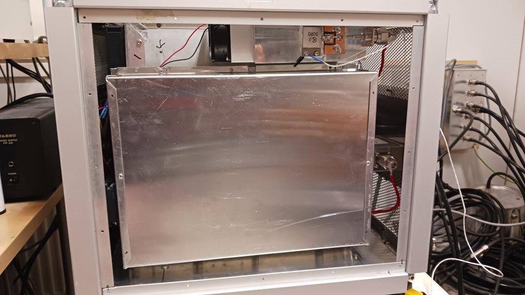
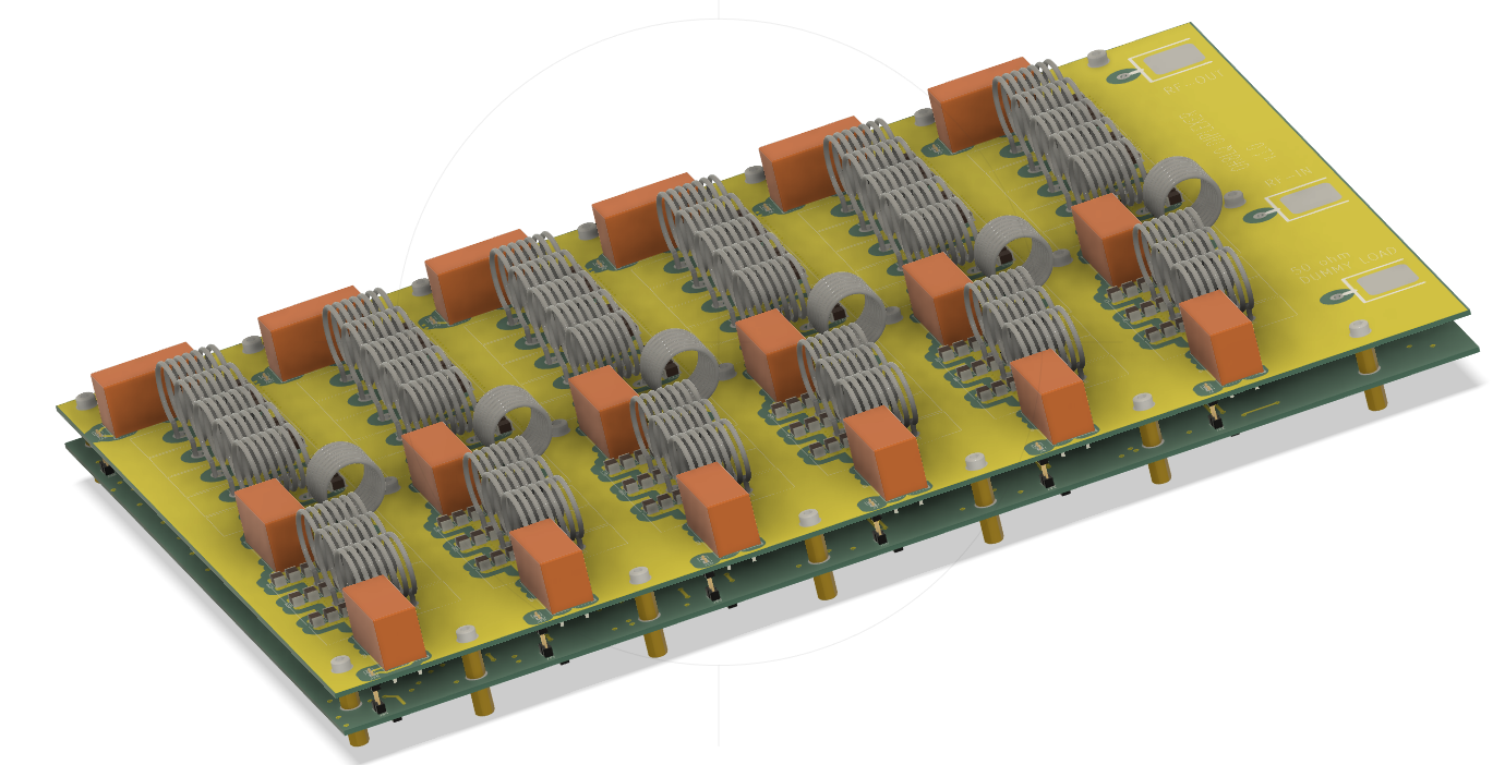
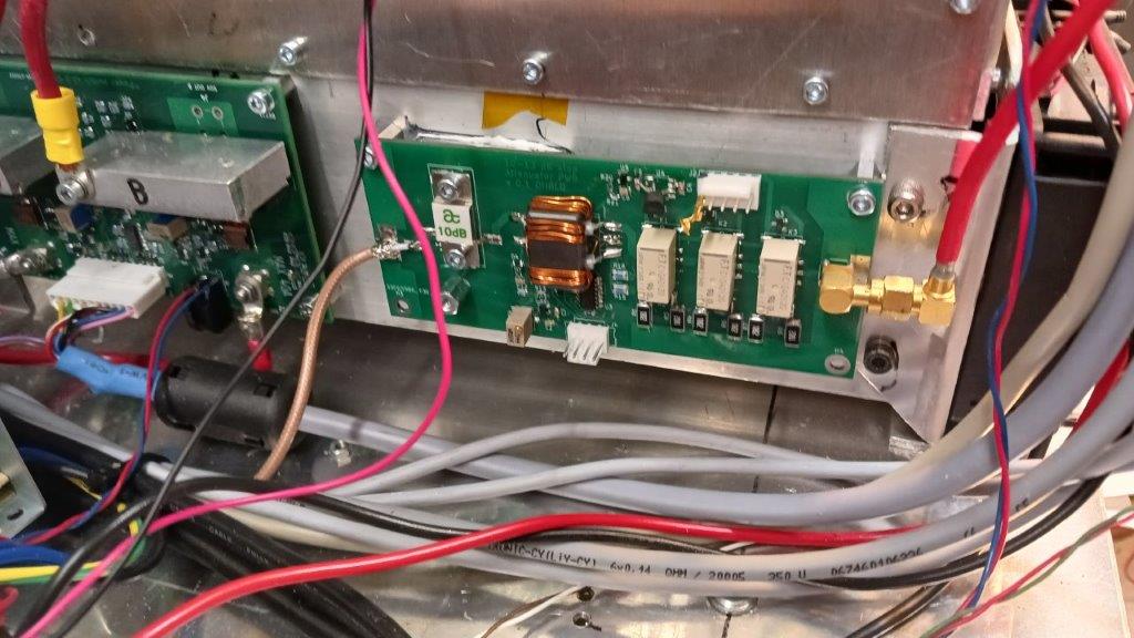
Diplexer and harmonic load
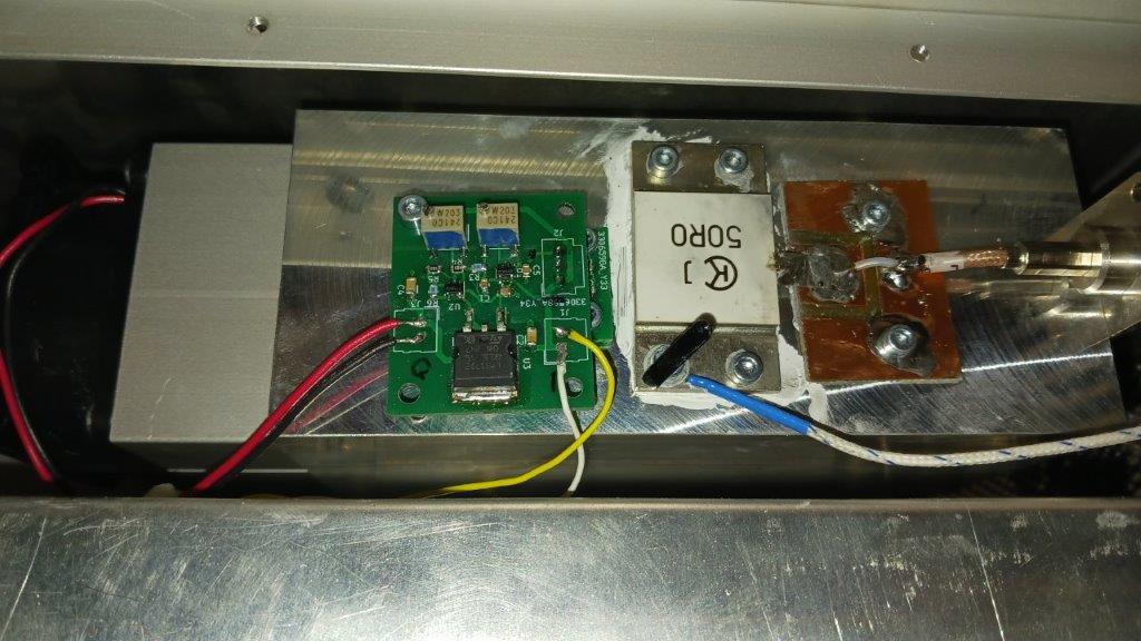
Harmonic load with FAN-control
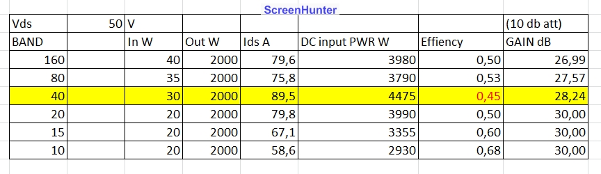
Effiency (at first test)
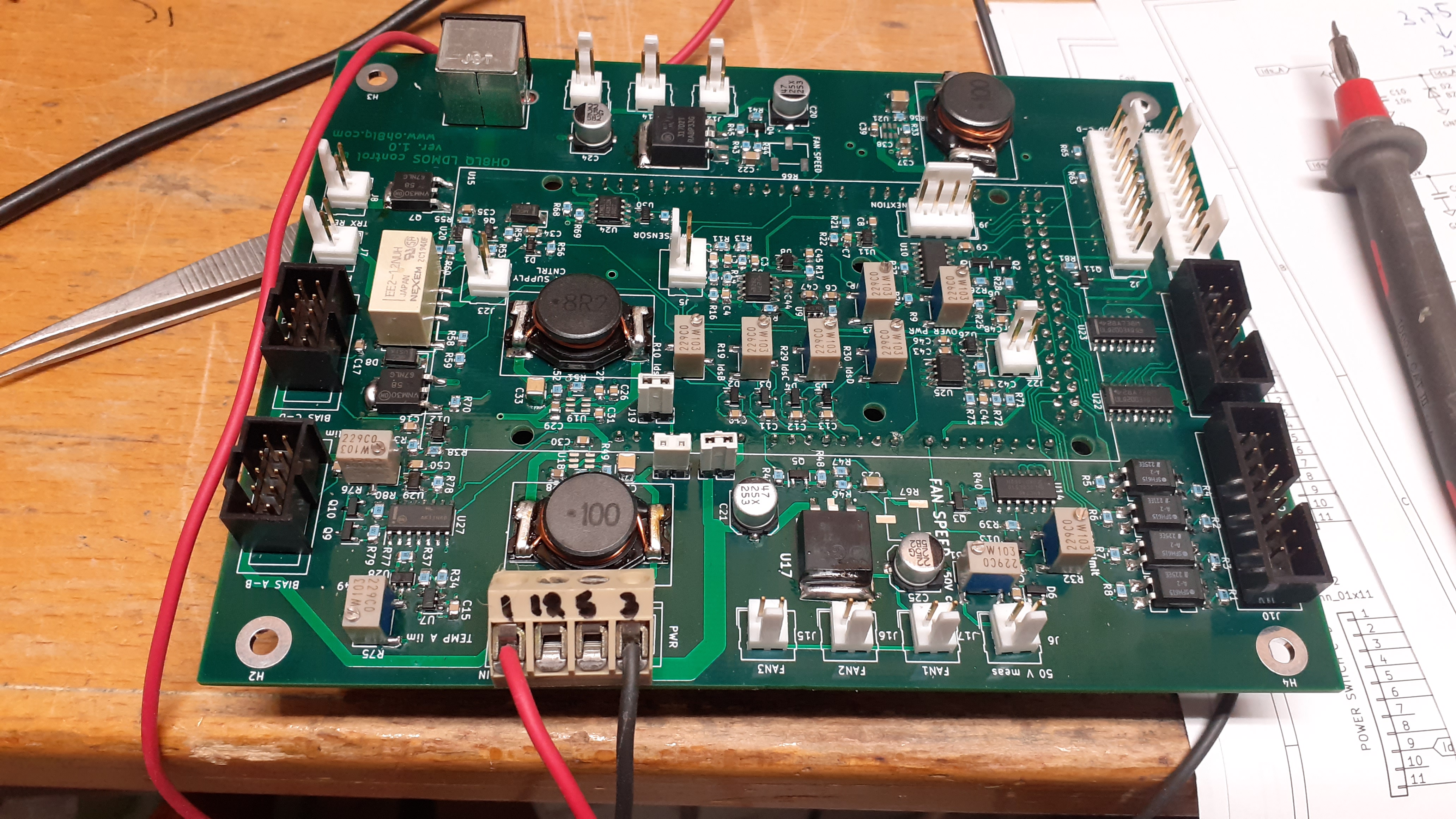
LDMOS Control board v1.0
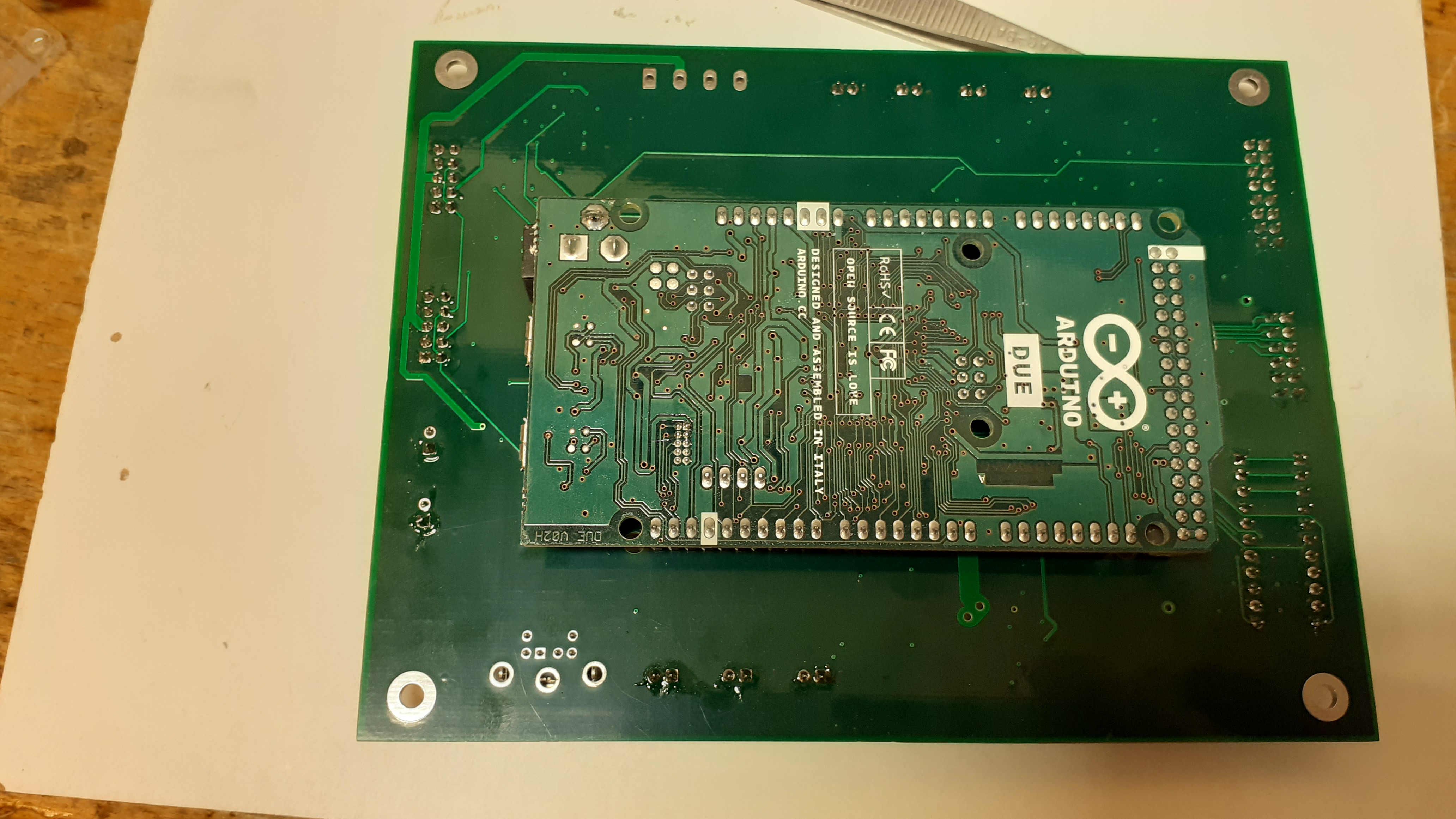
Arduino controller on board
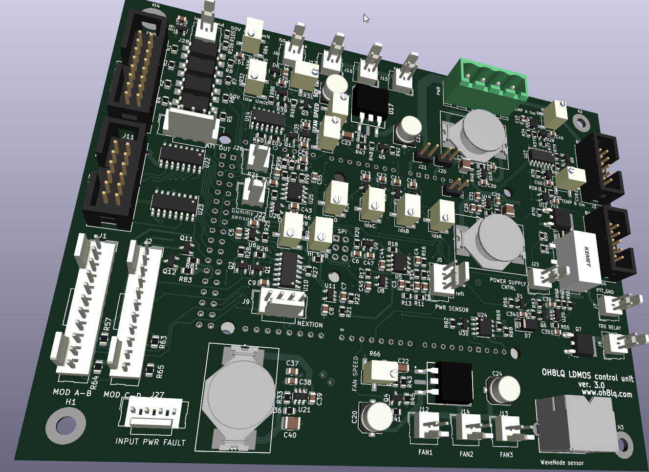
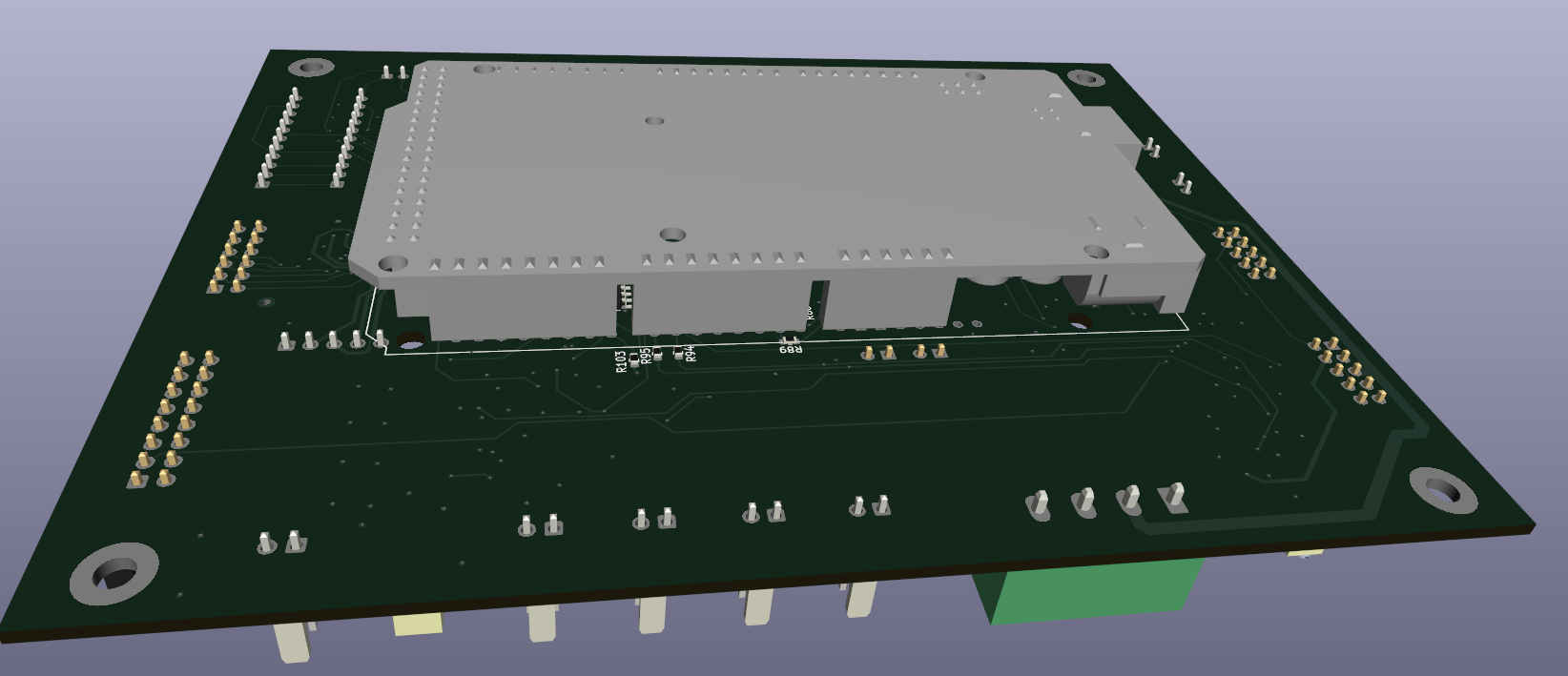

Latest one v5.0
I/O-list and calibration points
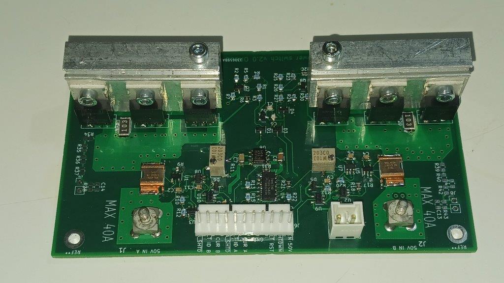

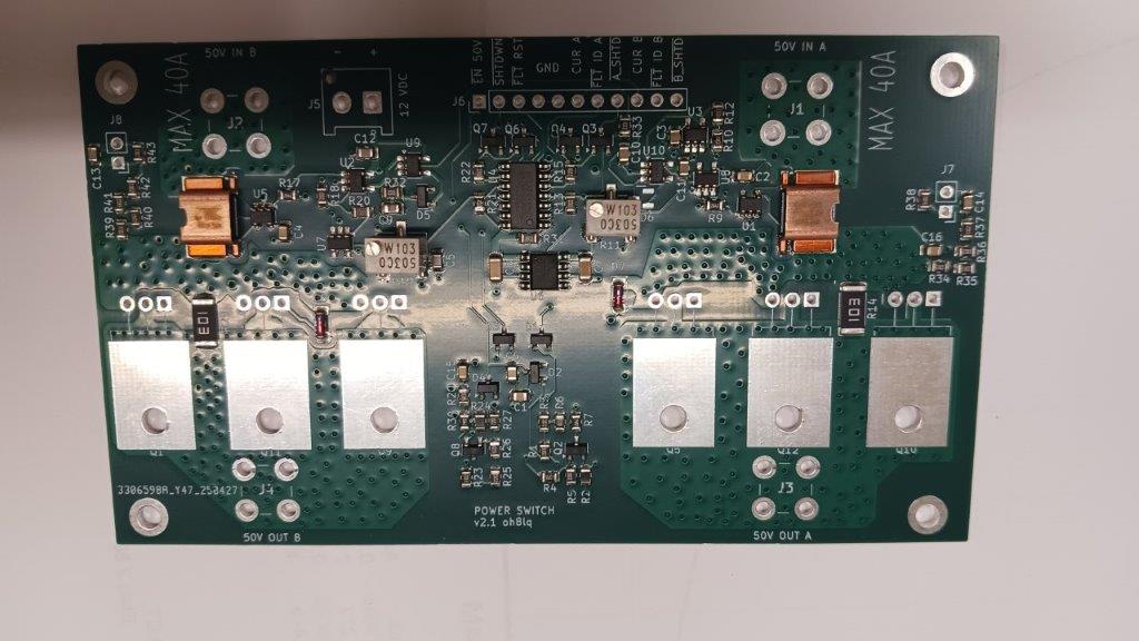
Latest version v2.1
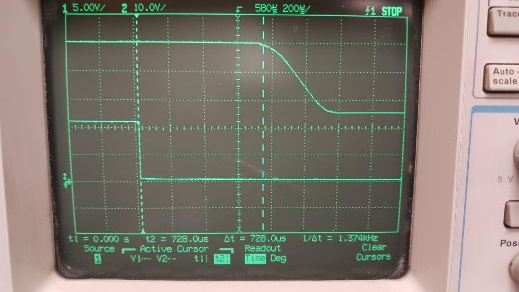
Shut down time. A_SHTD or B_SHTD pin go down.
I have some pcs. SMD already assembled PCB´s. Ask!
Price 48.00 EUR + shipping
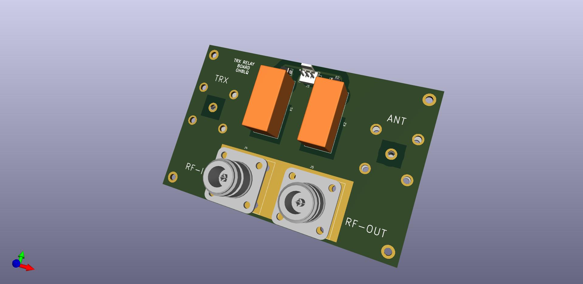
TRX-relay board
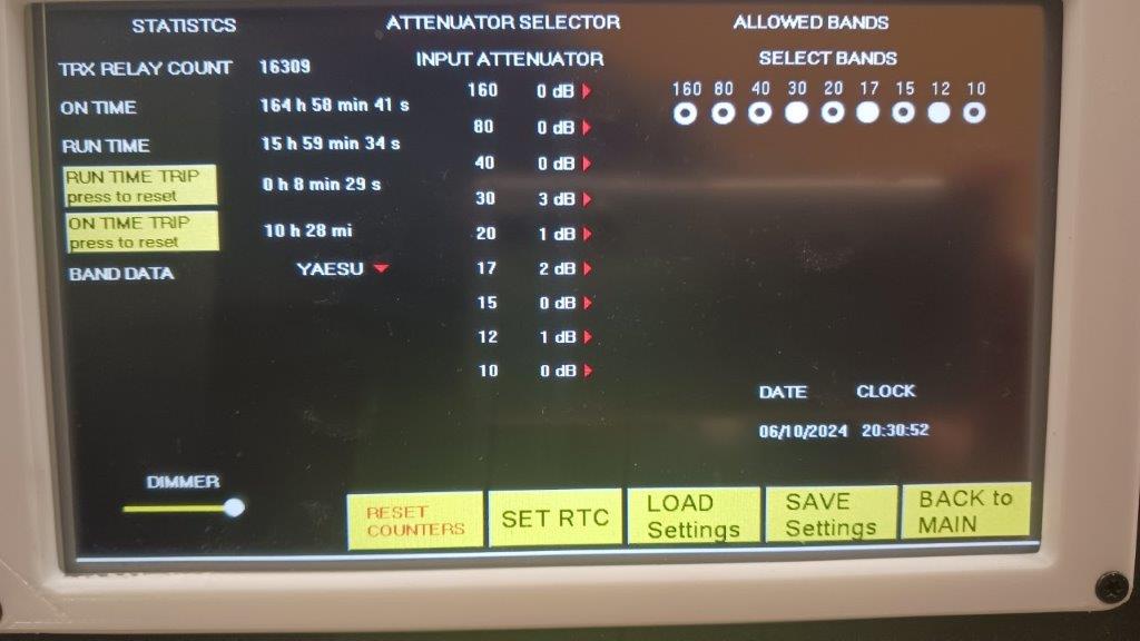
Input step attenuator

Input Attenuator and over drive detection
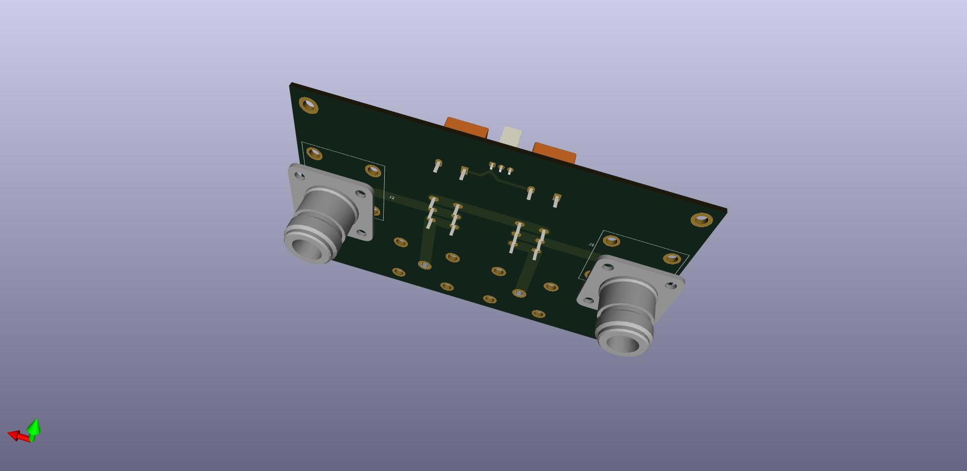
FAN speed controllel with LM35-sensor
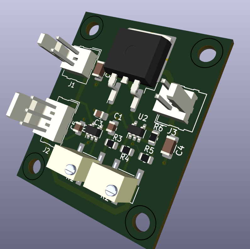
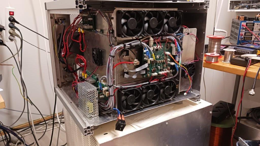
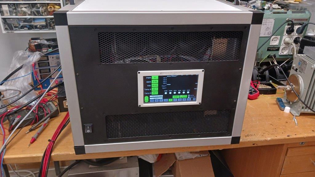
Almost ready to use
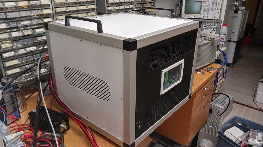
Added handles, weights approx. 30 kg
The amplifier was in real operation for the first time at the WPX CW 2023 contest. No problems found.
TFT-touchscreen UI first version
version (5.10.2024)
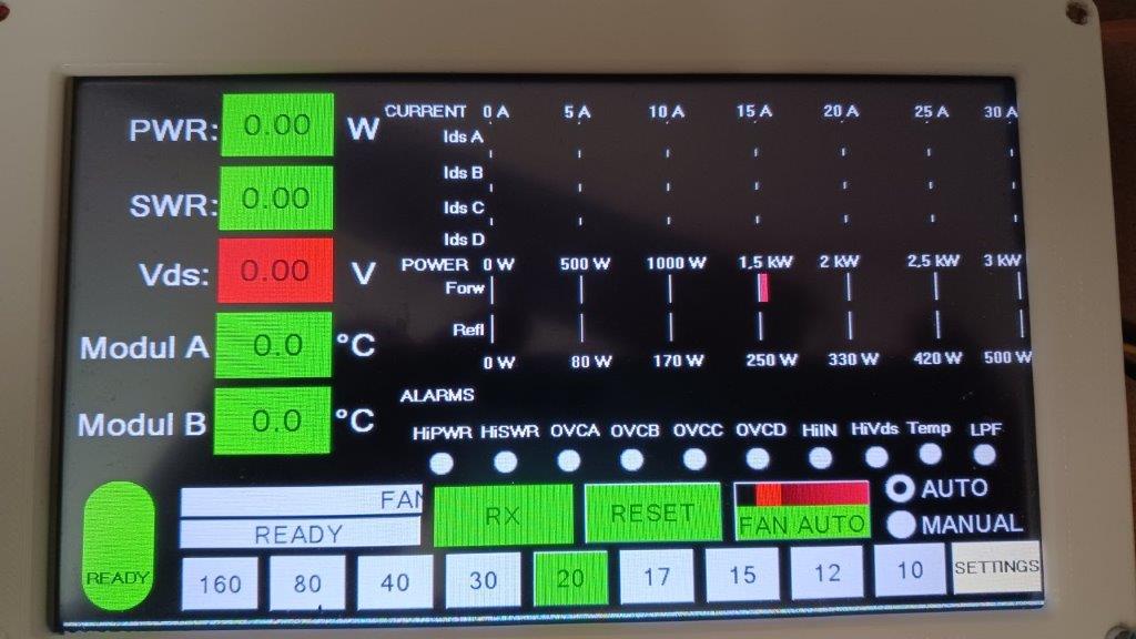
Early version UI
UI is under continuous development!
The goal is to have a version suitable for remote use at some point,
but the original design does not support it.
Look latest version Nextion LDMOS amplifier GUI
Three phase power with ESP120
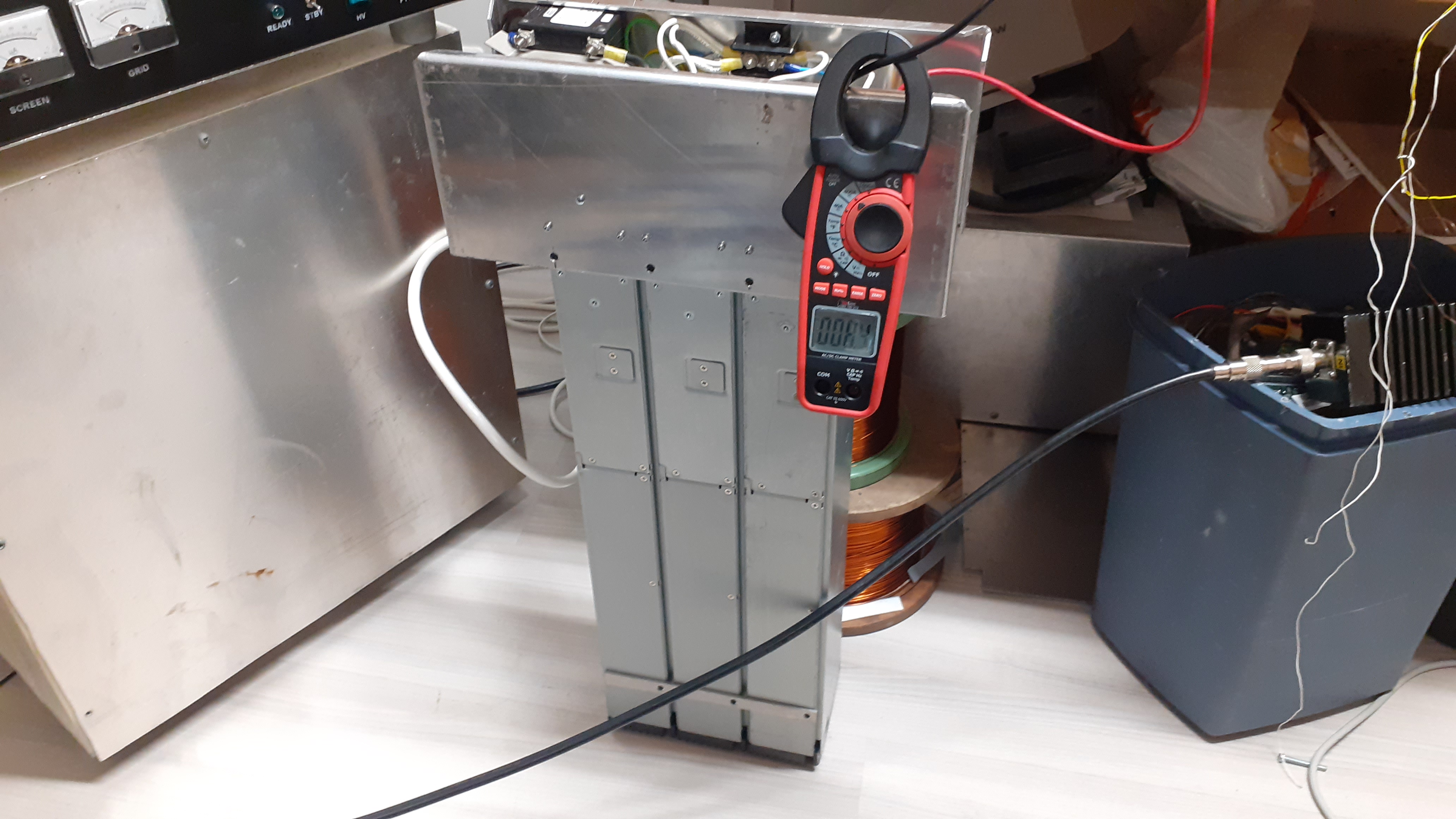
9 kW 50 V three-phase power supply ESP120
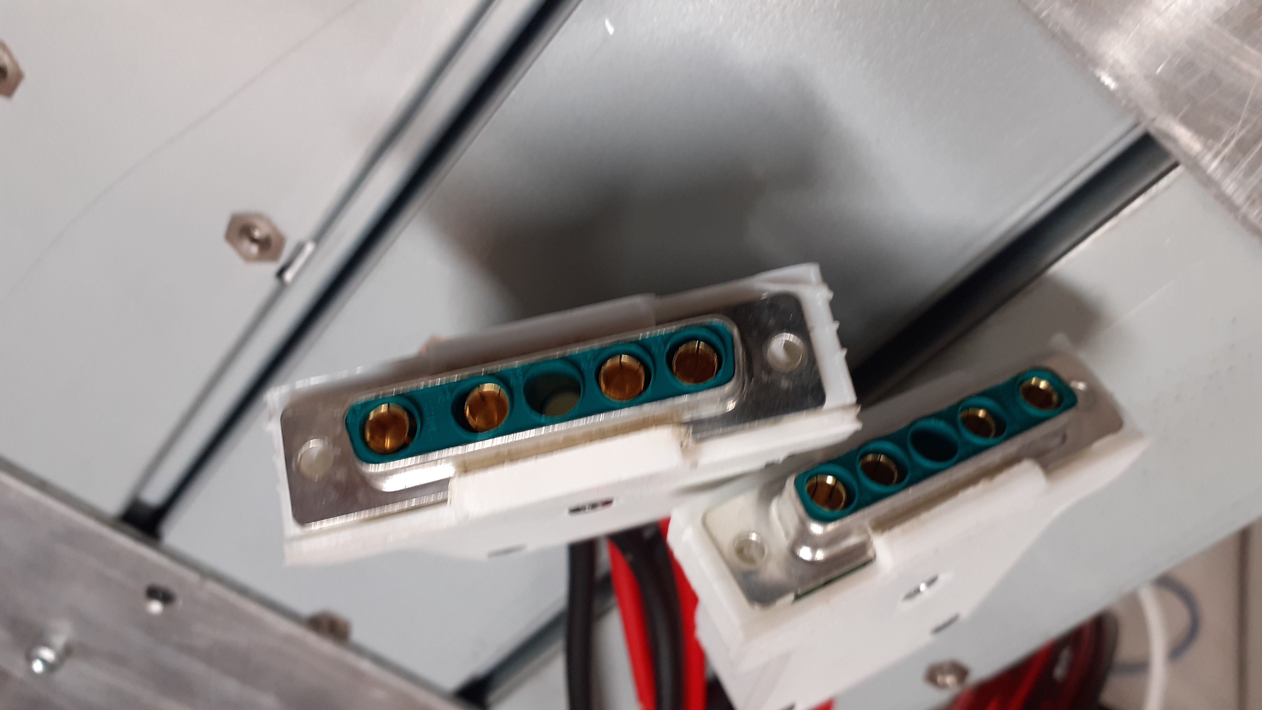
Power connectors
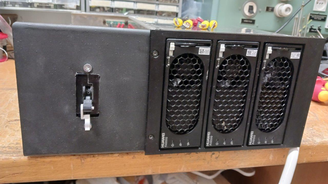
Three phase power supply with Huawei
Three-phase power supply from three Huawei R4850G2 power supplies connected in parallel. Maximum power about 9 kW.Why three power sources when one or two would be enough? In three phase system, loading one phase would cause a so-called bias load to the power grid.
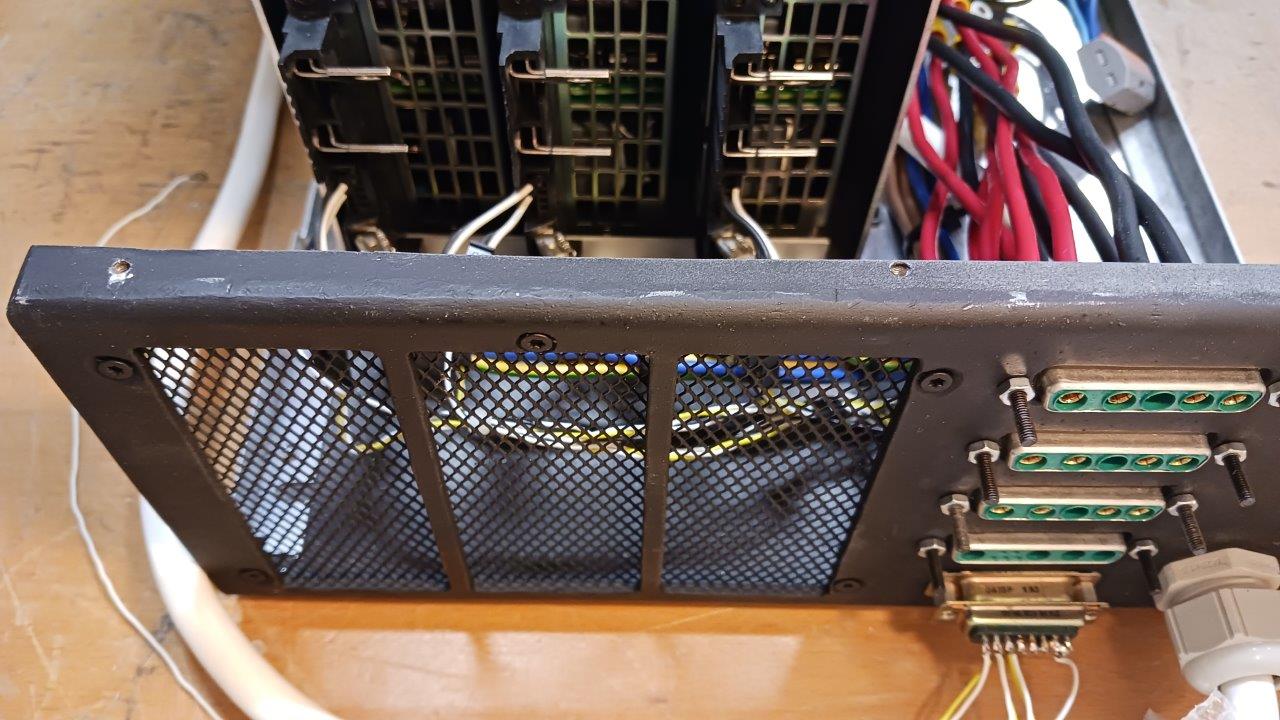
DC output connectors and D15 connector CAN bus for control
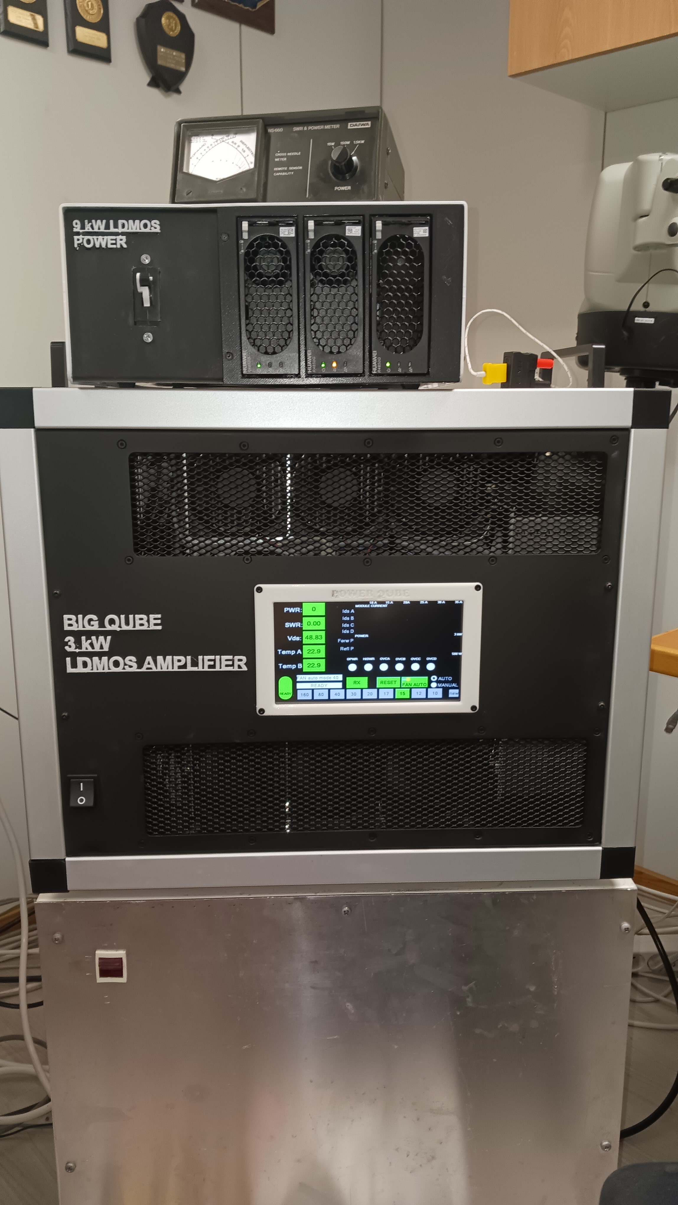
Linear + power :)
The large housing underneath is the power of the GU84 tube amplifier.
TO BE CONTINUE....