Vds overcurrent protection and current measurement board
The circuit board has Ids current measurement functions, as well as fast shutdown in overcurrent situations.
The overcurrent can be adjusted as desired with a trimmer. Vds voltage on/off control. Locked shutdown in overcurrent situations. Output signal indicating locking. The locking is removed by resetting with a reset signal.
One board has two separate protection/measurement lines. The board is suitable for two amplifiers containing 1-2 RF modules.
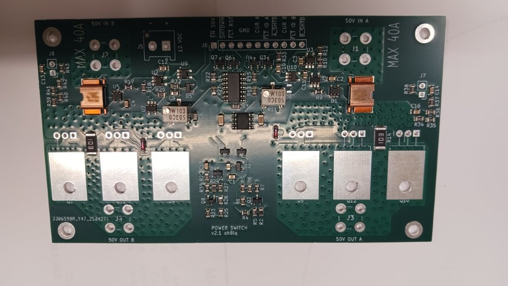
The board is available with SMD components pre-assembled.
Page 1: Current Sensing and Shutdown Logic (Channels A and B)
This page contains the heart of the protection mechanism. The board is split into two identical channels (A and B), allowing independent protection for two separate LDMOS transistors or circuits:
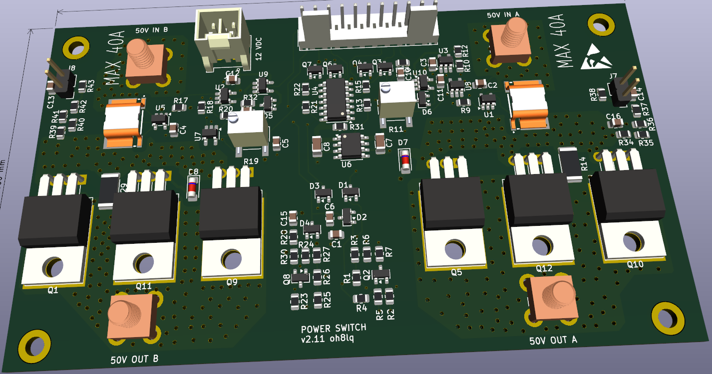
- Current Sensing: Current flows in through the IN_+50VDC connector and passes through a high-precision shunt resistor (WSL4026, 1 mΩ). An INA169 or ZXCT1084 IC measures the voltage drop across the resistor and converts it into a current-proportional voltage.
- Resistors R9 and R17 set the maximum current limit.
- The calculation example on the schematic shows: 25 A of current corresponds to 3.12 V, and 40 A corresponds to 5.00 V on the A_CURRENT and B_CURRENT lines.
- Comparator and Latch (Trip Logic): The voltage is fed to a TL331 comparator and a 74HC74 D-flip-flop. If the current exceeds the set threshold, the flip-flop latches into a fault state and cuts off the drive lightning-fast.
- Power Switches (Power MOSFETs): Heavy-duty, parallel-connected P-channel Power MOSFETs (IXTP120P065T or SUP60061EL-GE3) act as the actual switch and electronic fuse. They cut off the 50 V supply to the OUT_+50VDC connectors. Use at over 50 V Vds SUP60061EL-GE3.
Page 2: Connectors and Voltage Regulation
This page details how the board physically connects to the rest of the system:
- Main Power Connectors (J1, J2, J3, J4): Heavy-duty 74651173R screw terminals designed for high currents on the 50 VDC inputs and outputs.
- Internal Operating Voltage (U6): An L78L05 linear regulator drops the +12V supply down to +5V for the board's onboard logic. If you have a 3V3 processor (like newer Arduinos), change the regulator to a 3V3 model.
- Control Connector J6 (11-pin male header): The bus through which the board communicates directly with the main motherboard (Control Board). The signals are:
- EN-50V (Enable 50V board)
- SHUTDWN (Open collector type emergency shutdown output)
- FAULT_RST (Logic level pull-up type input to reset the protection)
- GND
- A_CURRENT (Analog voltage signal for Channel A current)
- FAULT_ID_A (CMOS logic level indicator for a Channel A fault)
- A_SHTD and B_SHTD (Connected together so both A and B shutdown at the same time)
- B_CURRENT (Analog voltage signal for Channel B current)
- FAULT_ID_B (CMOS logic level indicator for a Channel B fault)