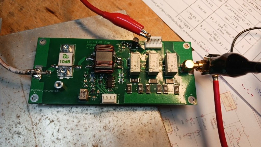
Input attenuator and over drive protection board
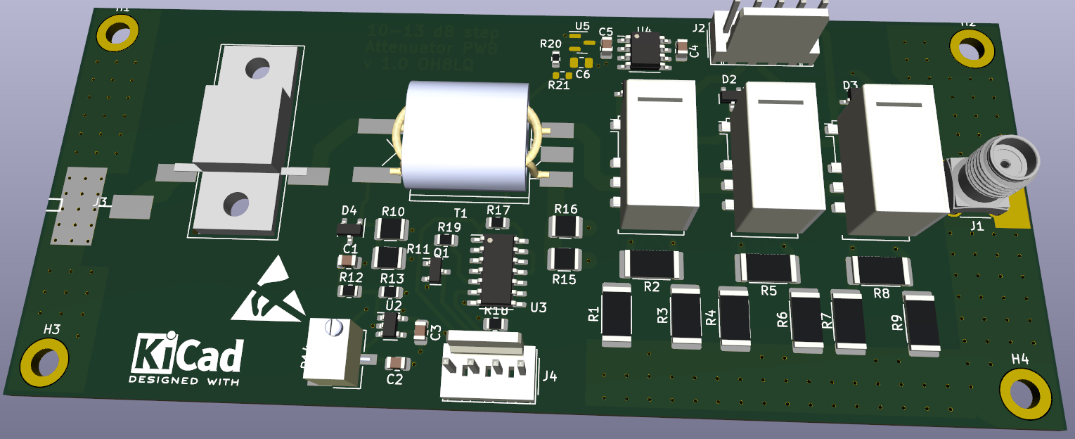
1. Control connections (J2 Connector)
- Relay Control (Attenuator selector): The main control board provides digital control signals to drive the physical relays on the attenuator board. This allows the system to automatically switch the band-specific attenuation values (dB) configured via the Nextion display (e.g., 160m–10m amateur bands).
- Common Ground (GND): Reference level for the signals.
2. Protection Interface (J4 Connector)
The attenuator board is also part of the emergency shutdown bus:
- This triggers an immediate emergency shutdown (Shutdown active LOW), causing the board to command the Power Switch board to cut off the main voltage supply before the LDMOS transistor gate can be destroyed.
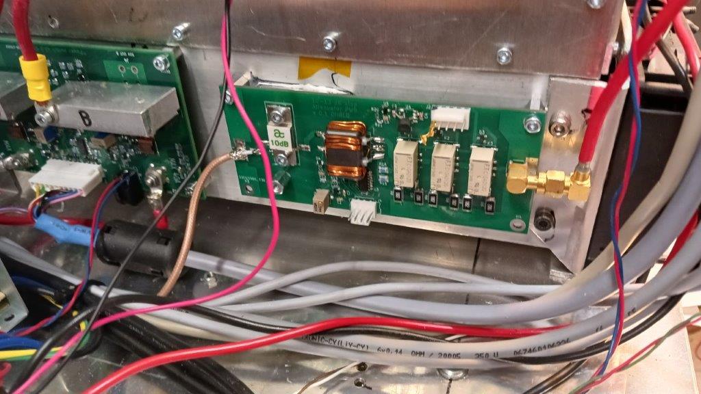
3. RF Cabling
Physically, the attenuator board is placed in the RF path right after the RF input connector on the rear panel (coming from the transceiver) and before the LDMOS amplifier pallets:
- RF In: Coaxial cable from the rear panel transceiver connector to the attenuator board.
- RF Out: Coaxial cable from the attenuator board forward to the LDMOS gate matching network.