HAM RADIO STATION OH8LQ

Main Menu

  • Home
  • Antennas
  • Hamshack
  • Making towers and antennas
  • OH8LQ since 1983
  • Myydään harustarvikkeita
  • For SALE

HAM Projects

  • 3 kW LDMOS linear amplifier
  • LDMOS amplifier control board
  • DC protection board
  • Input attenuator and protection board
  • LDMOS RF-pallet
  • GU84 autotune amp
  • 80 m Shorty Yagi
  • Winkeyer + SO2R box
  • Skimmer divider for FTdx101MP
  • 2x BLF188 HF-linear amplifier
  • 2x BLF188 HF-linear amplifier (rebuild 2026)
  • 4 Square Phasing box
  • Galvanic isolator (kalvanoitu erotin;))
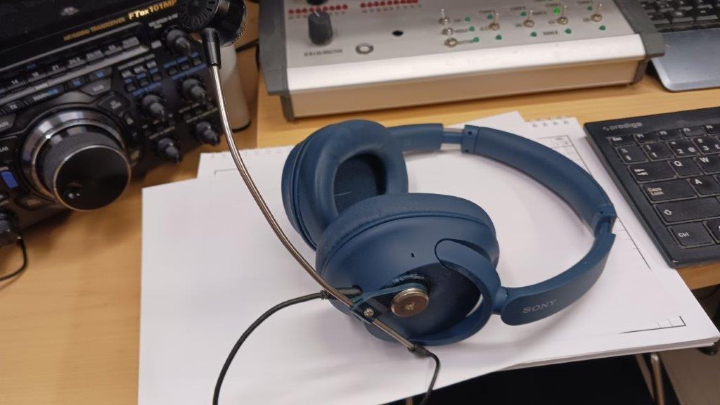
  • SONY WH-CH720N headset
  • BPF project
  • Relay box heater
  1. You are here:  
  2. Home
  3. Uncategorised

Uncategorised

BPF project

Details
Written by: Jari Ojala
Category: Uncategorised
Published: 05 January 2025
Hits: 1780


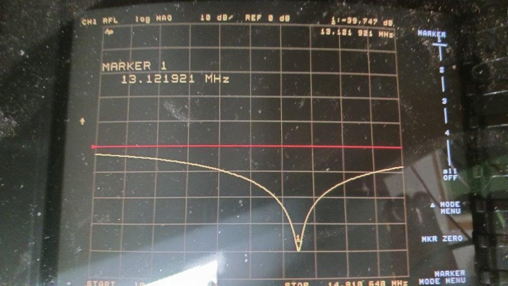
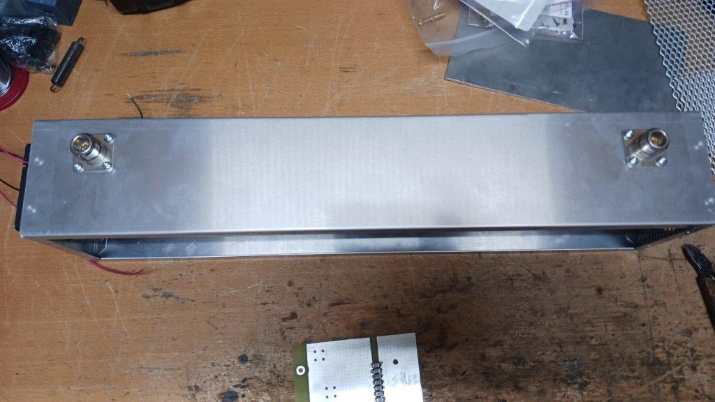
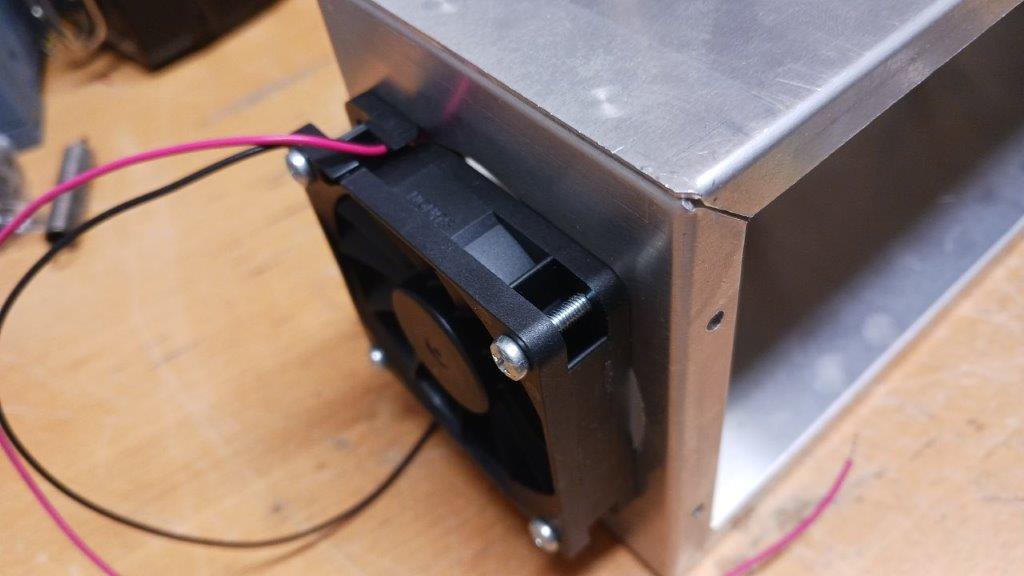
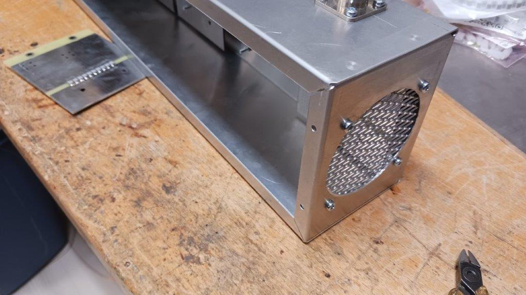
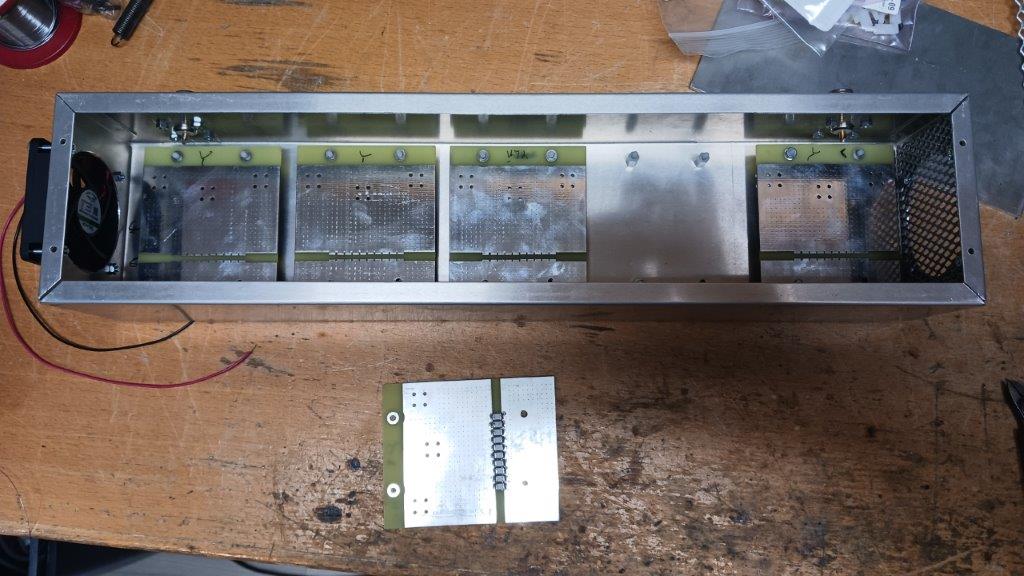
BPF Project


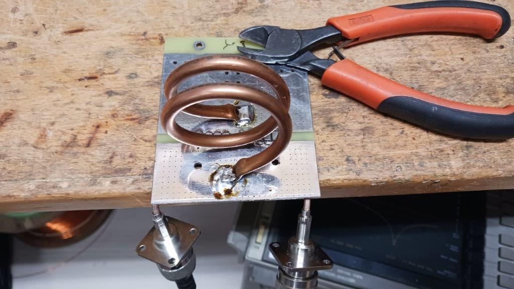
Parallel resonance circuit
20240807_102321.jpg


20240807_102336.jpg


20240807_095058.jpg


20240807_095046.jpg


20240807_095035.jpg


20240807_095015.jpg


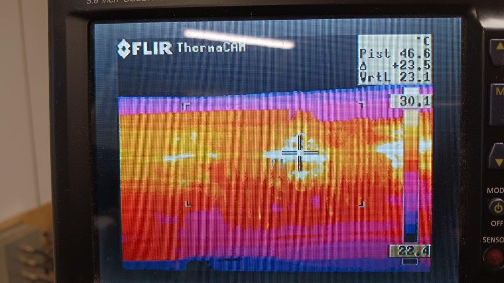
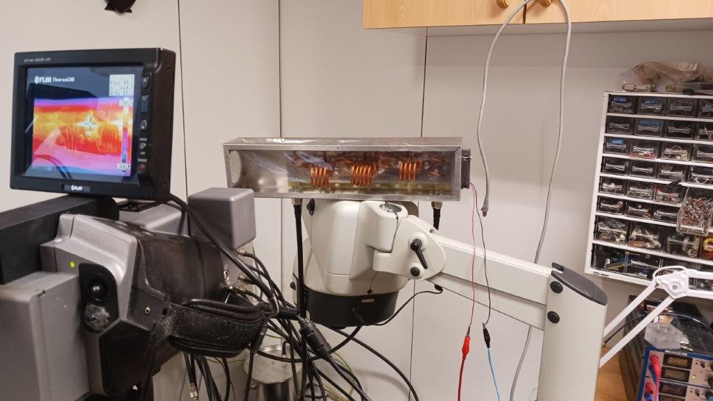
BPF testing with a thermal camera!
 

20240126_135200.jpg


20240126_135147.jpg


More information later in the future...


Input attenuator

Details
Written by: Jari Ojala
Category: Uncategorised
Published: 05 October 2024
Hits: 18376


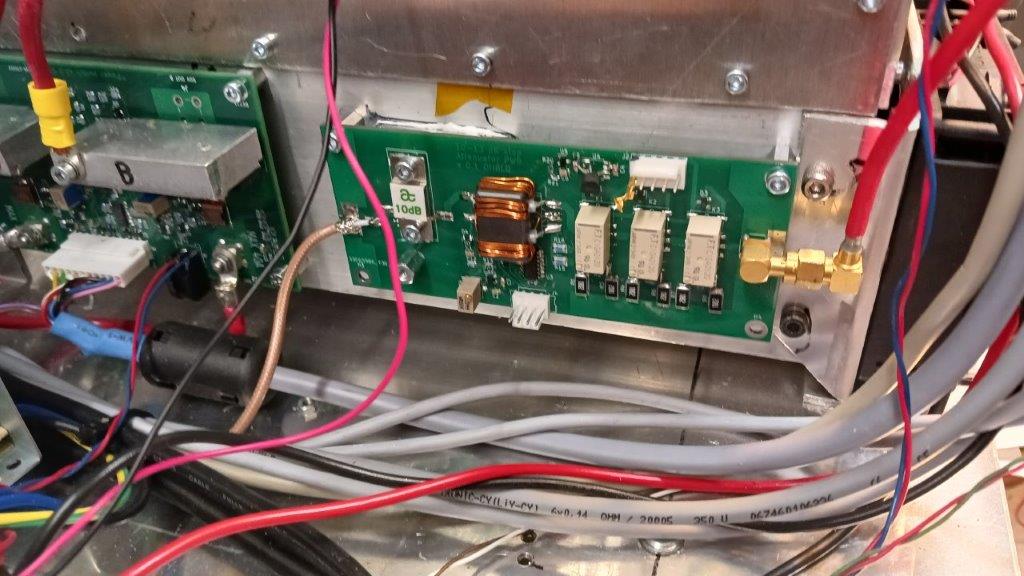
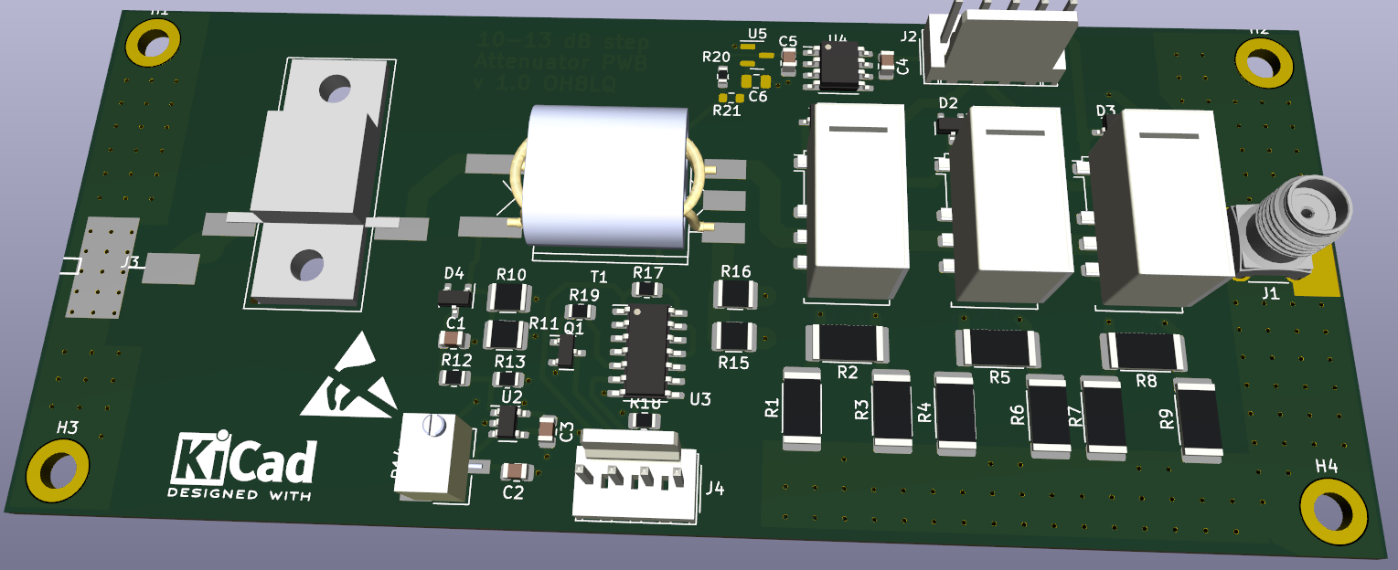
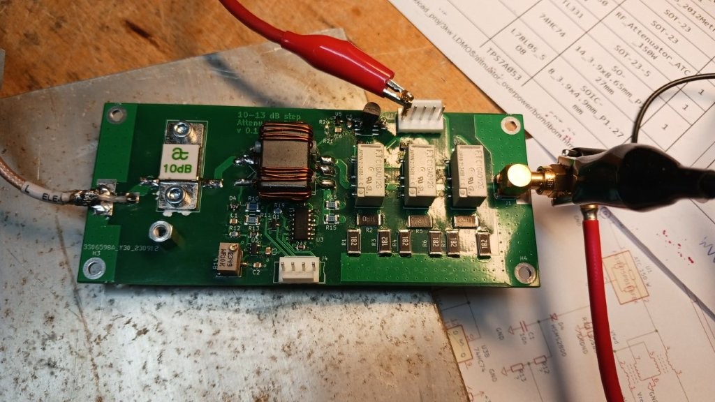
Input attenuator and over drive protection board
 

Attenuator_power_limiter_v1.0_SCH.png


1. Control  connections (J2 Connector)

  • Relay Control (Attenuator selector): The main control board provides digital control signals to drive the physical relays on the attenuator board. This allows the system to automatically switch the band-specific attenuation values (dB) configured via the Nextion display (e.g., 160m–10m amateur bands).
  • Common Ground (GND): Reference level for the signals.

2. Protection Interface (J4 Connector)

The attenuator board is also part of the emergency shutdown bus:

  • This triggers an immediate emergency shutdown (Shutdown active LOW), causing the board to command the Power Switch board to cut off the main voltage supply before the LDMOS transistor gate can be destroyed.

3. RF Cabling

Physically, the attenuator board is placed in the RF path right after the RF input connector on the rear panel (coming from the transceiver) and before the LDMOS amplifier pallets:

  • RF In: Coaxial cable from the rear panel transceiver connector to the attenuator board.
  • RF Out: Coaxial cable from the attenuator board forward to the LDMOS gate matching network.
Input_protection_and_atteunuator.jpg


Schema

BOM

Assembly

SONY WH-CH720N headset

Details
Written by: Jari Ojala
Category: Uncategorised
Published: 17 November 2023
Hits: 3047

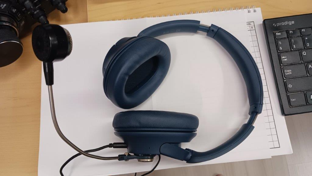
Heil BM10 boom Mic added


Galvanic isolator (kalvanoitu erotin;))

Details
Written by: Jari Ojala
Category: Uncategorised
Published: 17 October 2023
Hits: 3562


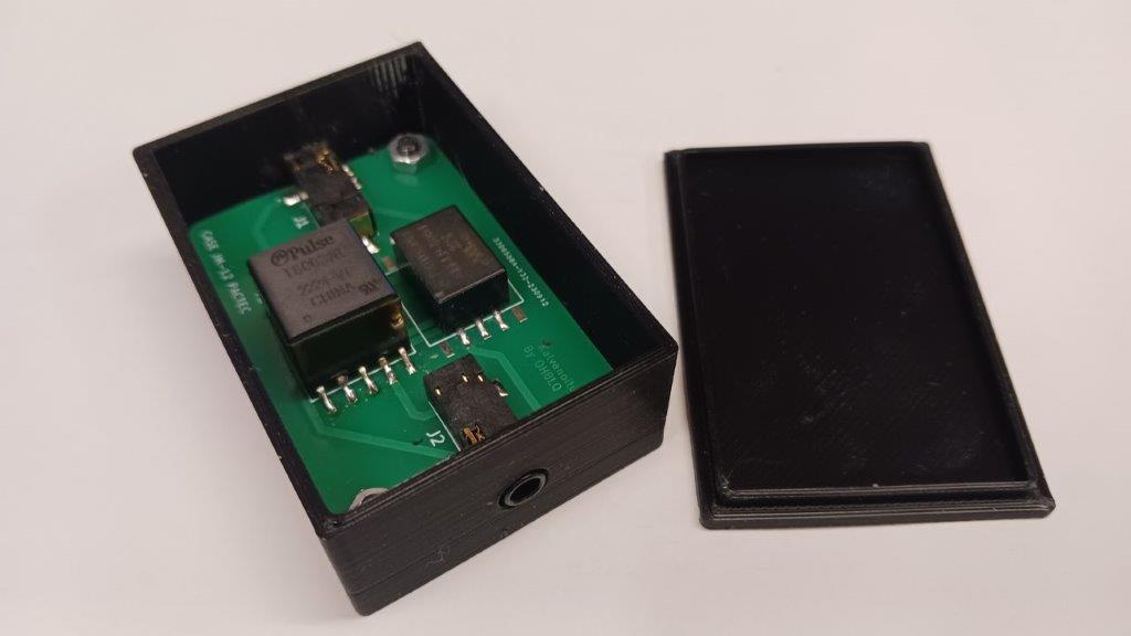
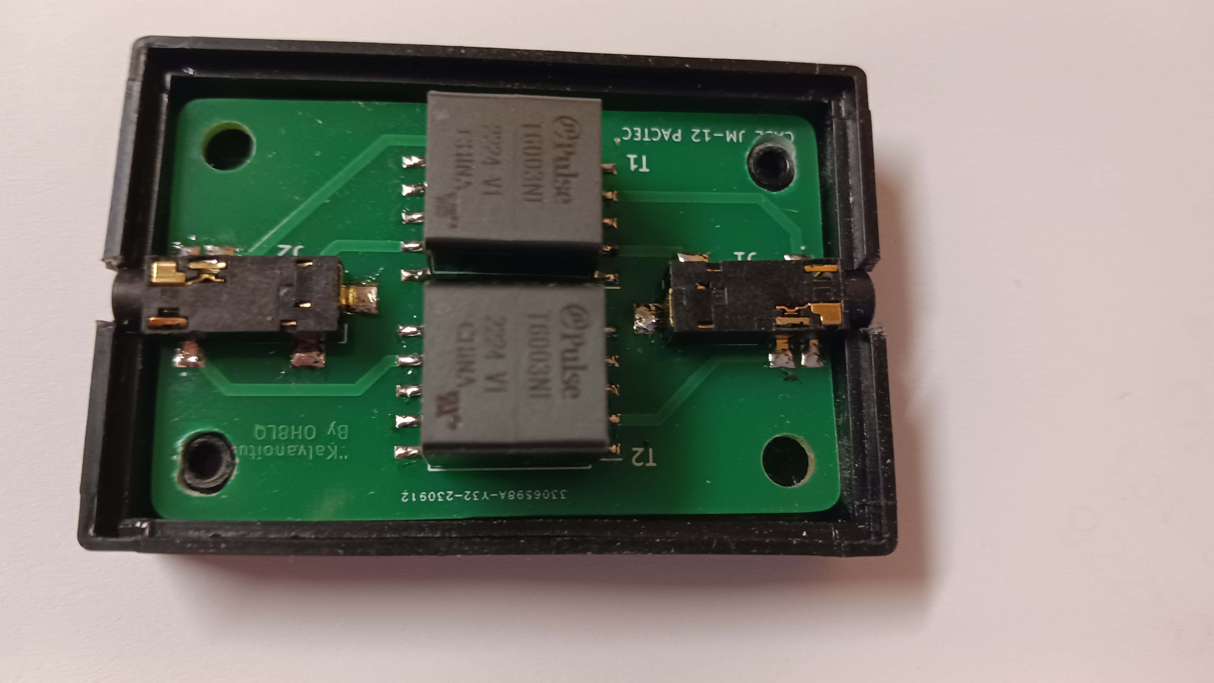
Galvanic stereo Isolator/

"galvanoitu erotin"

The galvanic isolator works up to approx. 100-4000 Hz. The transformer characteristics limit the bandwidth.
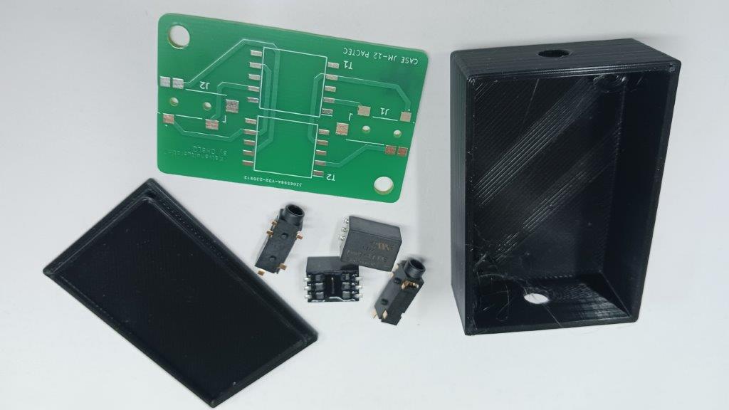
 

BOM/LAYOUT


20241031_171937.jpg

Parts


20241031_171815.jpg

Complete isolator at 3D printed case

Page 3 of 11

  • 1
  • 2
  • 3
  • 4
  • 5
  • 6
  • 7
  • 8
  • 9
  • 10

VIDEO

  • Tower works at OH8LQ
  • Solder LDMOS
  • 42 m tower goes up
  • Ice droppin by drone PART I
  • Ice droppin by drone PART II
  • LDMOS amplifier GUI

Other projects

  • Solar power plant
  • 22 kW diesel generator project
  • Forest trailer
  • Harbor trailer

Presentations

  • LDMOS linear amplifiers (Finish)
  • SDR and CW Skimmer
  • OH Contests (kesäleiri 2022)