Uncategorised
- Details
- Written by: Jari Ojala
- Category: Uncategorised
- Hits: 25137
QSL info
OH8L LoTW, OQRS and direct (SASE)
OH8LQ Lotw and direct (SASE)
OG73X LoTW, OQRS and direct (SASE)

- Details
- Written by: Jari Ojala
- Category: Uncategorised
- Hits: 439
How do you set up N1MM+ for SO2R operation using the FTdx101's built-in USB audio codecs?
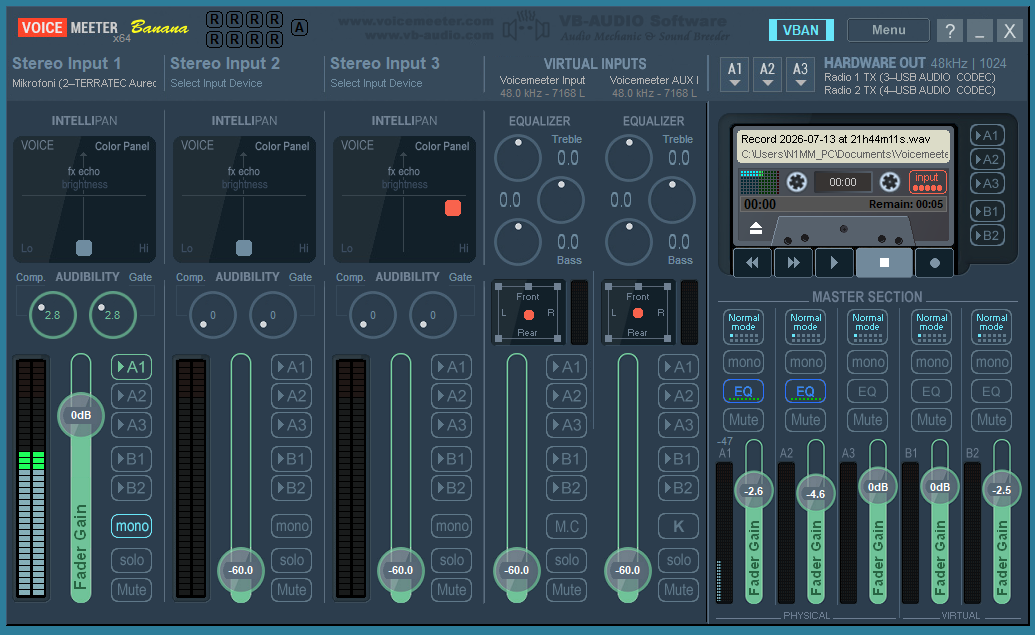
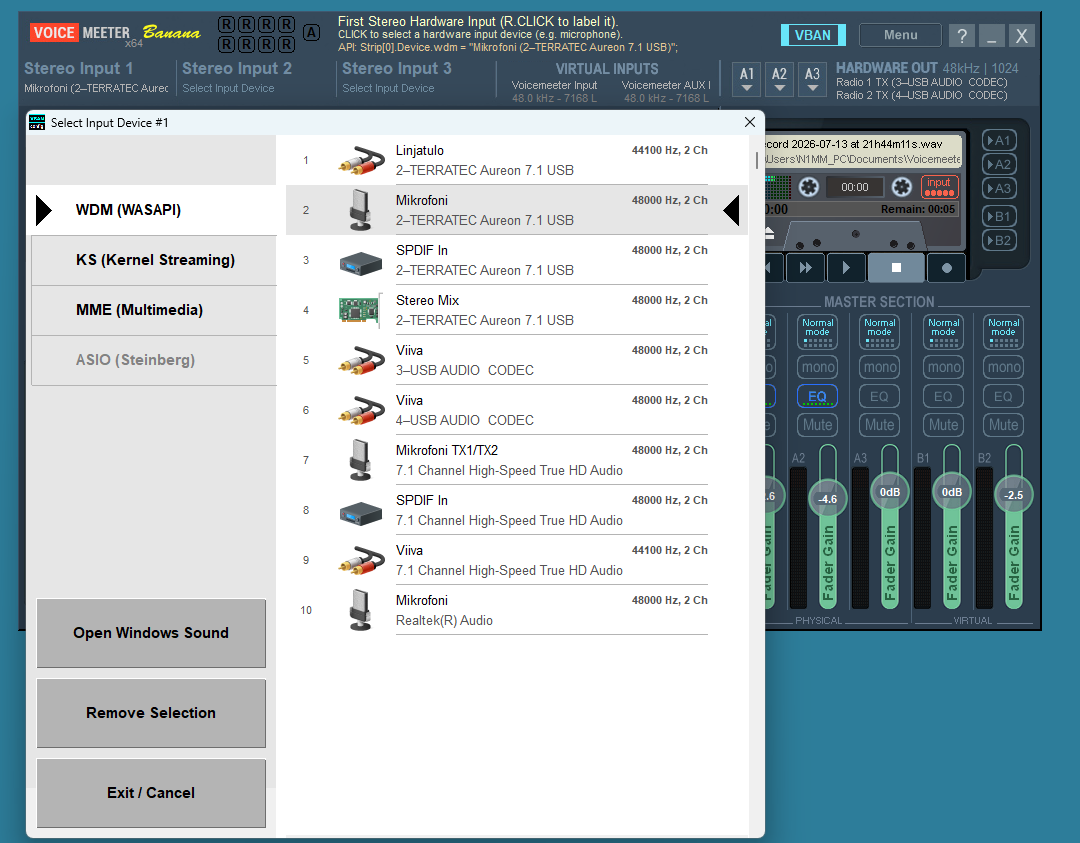
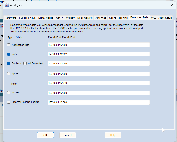
The station uses two FTdx101 radios, utilizing their internal USB audio interfaces to achieve SO2R capability. The microphone connects to the computer's sound card, and N1MM+ must route the microphone audio to the radio currently holding TX focus. Since N1MM+ cannot handle this routing directly, a virtual audio path is required between the computer's sound card and the radios' USB codecs. Voicemeeter can manage this audio routing, but a script is needed between N1MM+ and Voicemeeter to relay the TX focus status. This information is obtained by monitoring N1MM+'s radio UDP messages and extracting the focus data. (Note: N1MM+ messages themselves are routed directly to the correct radios without requiring additional software.)
There is one drawback compared to using the radio's front-panel microphone input: the radio's internal TX audio equalizer is bypassed. While Voicemeeter includes an equalizer, it only affects the live microphone signal and does not apply to the transmission of pre-recorded audio messages.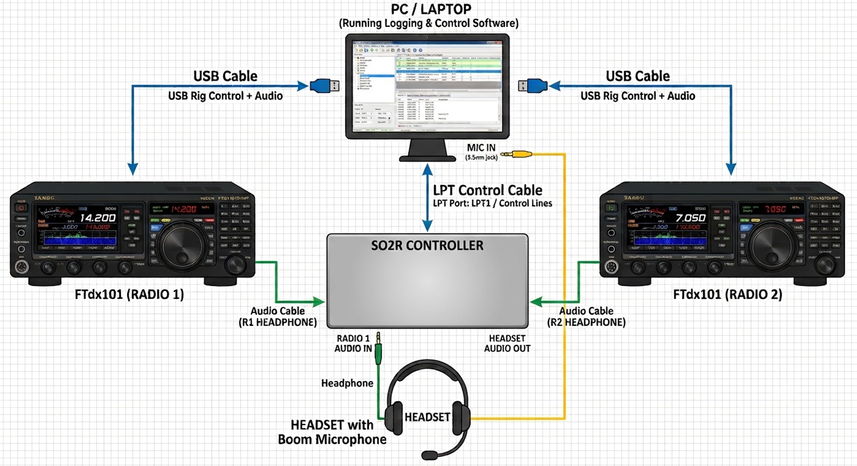
Signal & Control Flows
1. Audio Path (Audio Flow)
- The Microphone feeds analog/USB audio into a VoiceMeeter Hardware Input strip (e.g., Strip 1).
- The input strip is routed to two separate output buses:
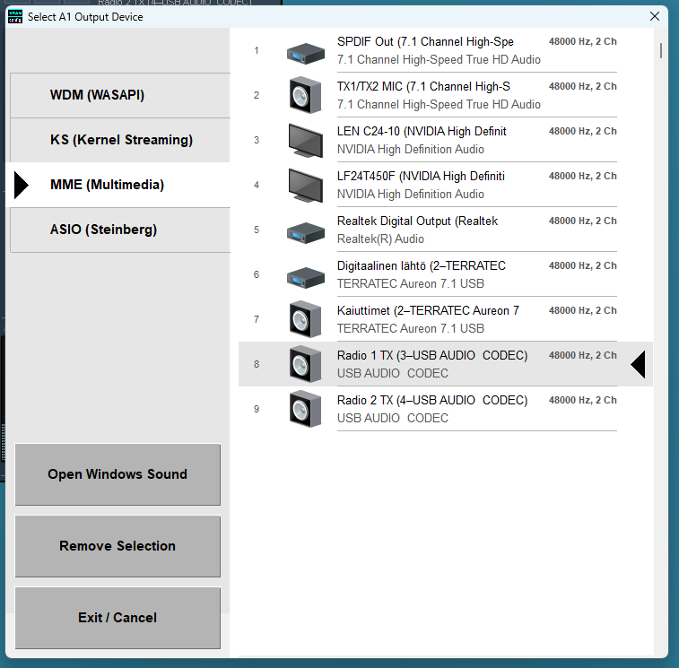
- Bus A1 Radio 1 (Sound Card / Virtual Audio Cable 1)
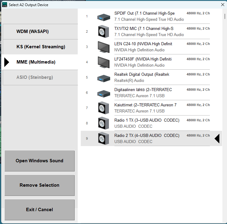
- Bus A2 Radio 2 (Sound Card / Virtual Audio Cable 2)
- VoiceMeeter dynamically keeps one bus active while muting the other based on commands from the script.
2. Control Signal (Control Flow)
- N1MM+: Broadcasts real-time operational status over a UDP port (e.g., Radio status or Radio focus packets formatted in XML/JSON).
- Python Script:
- Listens to N1MM+'s UDP broadcasts in the background using the standard socket library.
- Parses the incoming packet to determine which radio currently holds TX focus (Radio 1 or Radio 2).
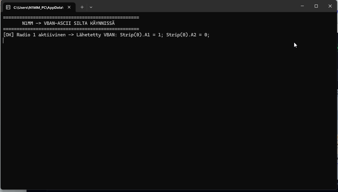
- Sends commands via the VoiceMeeter API (e.g., using voicemeeter-api or direct Remote DLL calls) to switch routing on the fly:
- TX Radio 1 Active: Strip[0].A1 = 1, Strip[0].A2 = 0
- TX Radio 2 Active: Strip[0].A1 = 0, Strip[0].A2 = 1
- Dowload N1MM_bridge.py
Routing Logic Matrix
| N1MM+ TX Focus | VoiceMeeter Python Command | Radio 1 Audio | Radio 2 Audio |
| Radio 1 | Strip(0).BusA1 = True, Strip(0).BusA2 = False | Active (TX) | Muted |
| Radio 2 | Strip(0).BusA1 = False, Strip(0).BusA2 = True | Muted | Active (TX) |
CONTINUE........
- Details
- Written by: Jari Ojala
- Category: Uncategorised
- Hits: 3204
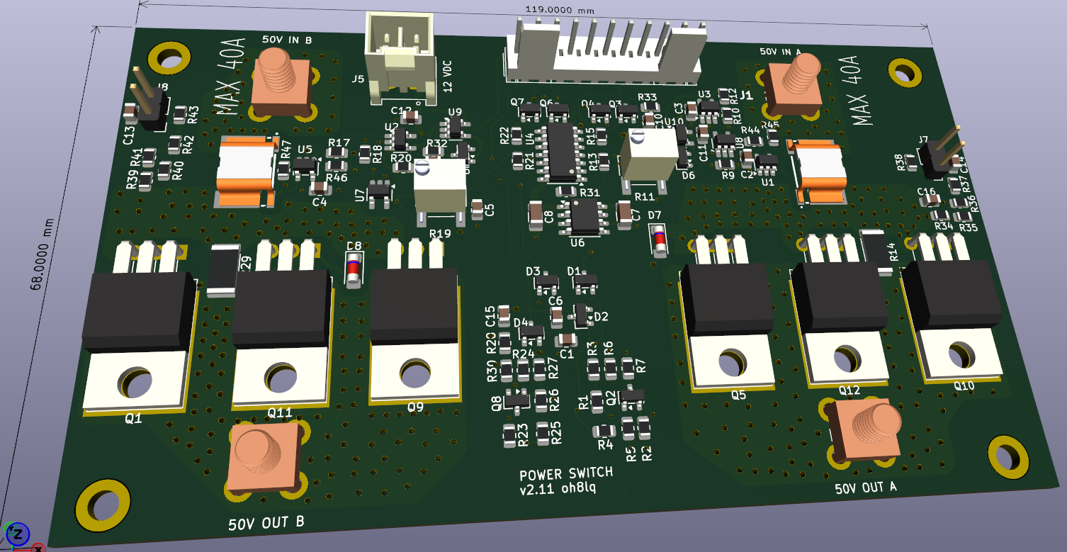
Vds overcurrent protection and current measurement board
The circuit board has Ids current measurement functions, as well as fast shutdown in overcurrent situations.
The overcurrent can be adjusted as desired with a trimmer. Vds voltage on/off control. Locked shutdown in overcurrent situations. Output signal indicating locking. The locking is removed by resetting with a reset signal.
One board has two separate protection/measurement lines. The board is suitable for amplifiers containing 1-2 RF modules.
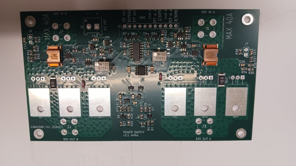
The board is available as a pre-assembled SMD version
Page 1: Current Sensing and Shutdown Logic (Channels A and B)
This schema page contains the heart of the protection mechanism. The board is split into two identical channels (A and B), allowing independent protection for two separate LDMOS transistors or circuits:
- Current Sensing: Current flows in through the IN_+50VDC connector and passes through a high-precision shunt resistor (WSL4026, 1 mΩ). An INA169 (abs max voltage 75 V), (in case of over 60 V, use INA293A1 (A=20) only version 2.11 and higher) , IC measures the voltage drop across the resistor and converts it into a current-proportional voltage.
- Resistors R9 and R17 set the INA169 maximum amplification, 24k9 set A=25.
- The calculation example on the schematic shows: 25 A of current corresponds to 3.12 V, and 40 A corresponds to 5.00 V on the A_CURRENT and B_CURRENT lines.
- Comparator and Latch (Trip Logic): The voltage is fed to a TL331 comparator and a 74HC74 D-flip-flop. If the current exceeds the set threshold, the flip-flop latches into a fault state and cuts off the drive lightning-fast. Cut off current sets by R11 and R19 trimmers.
- Power Switches (Power MOSFETs): Heavy-duty, parallel-connected P-channel Power MOSFETs (IXTP120P065T or SUP60061EL-GE3) act as the actual switch and electronic fuse. They cut off the 50 V supply to the OUT_+50VDC connectors. For Vds over 50 V, use SUP60061EL-GE3.
Page 2: Connectors and Voltage Regulation
This schema page details how the board physically connects to the rest of the system:
- Main Power Connectors (J1, J2, J3, J4): Heavy-duty 74651173R screw terminals designed for high currents on the 50 VDC inputs and outputs.
- Internal Operating Voltage (U6): An L78L05 linear regulator drops the +12V supply down to +5V for the board's onboard logic. If you have a 3V3 processor (like newer Arduinos), change the regulator to a 3V3 model.
- Control Connector J6 (11-pin male header): The bus through which the board communicates directly with the main motherboard (Control Board). The signals are:
- EN-50V (Enable 50V board)
- SHUTDWN (Open collector type emergency shutdown output)
- FAULT_RST (Logic level pull-up type input to reset the protection)
- GND
- A_CURRENT (Analog voltage signal for Channel A current)
- FAULT_ID_A (CMOS logic level indicator for a Channel A fault)
- A_SHTD and B_SHTD (Connected together so both A and B shutdown at the same time)
- B_CURRENT (Analog voltage signal for Channel B current)
- FAULT_ID_B (CMOS logic level indicator for a Channel B fault)
- Details
- Written by: Jari Ojala
- Category: Uncategorised
- Hits: 1169
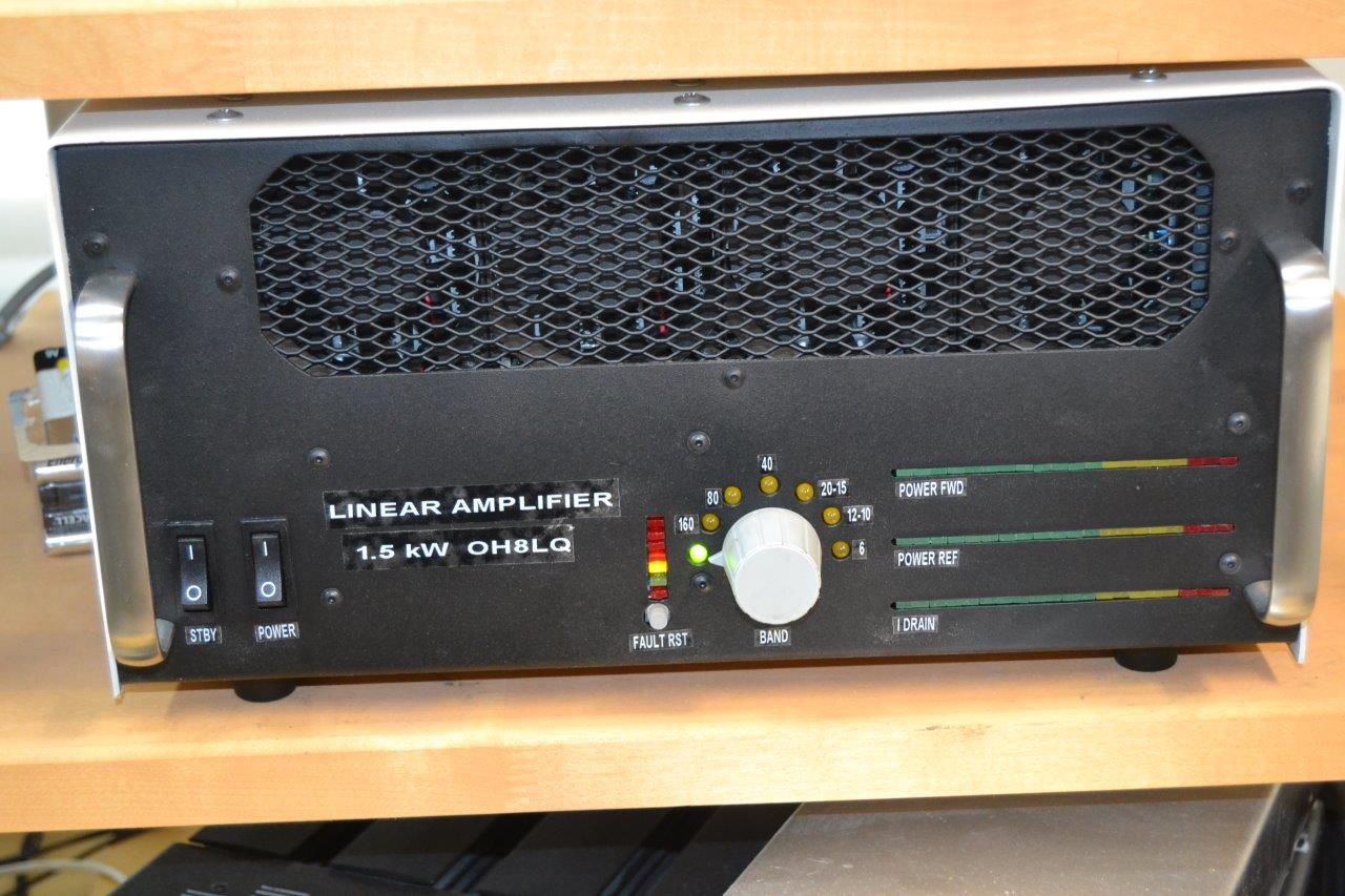
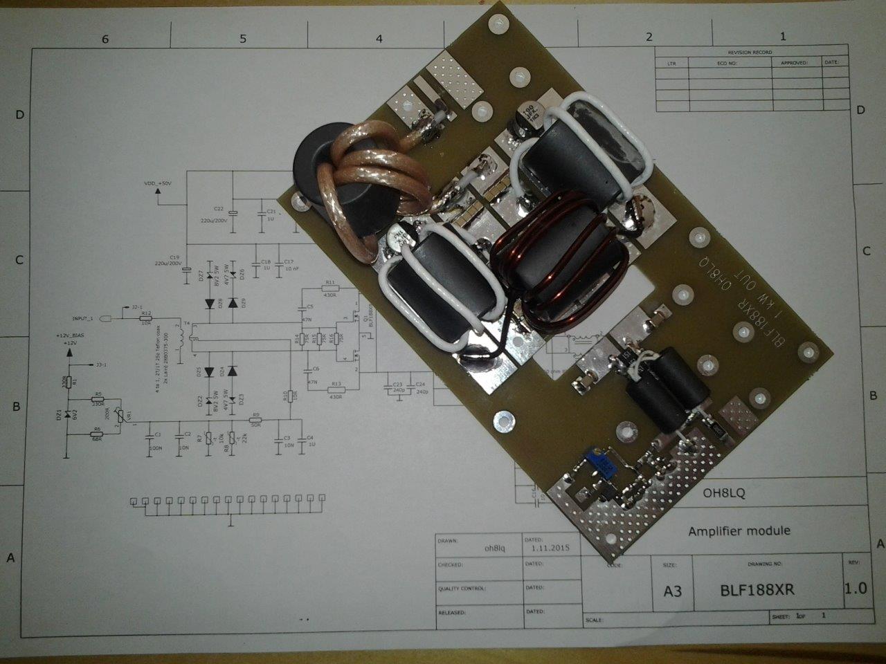
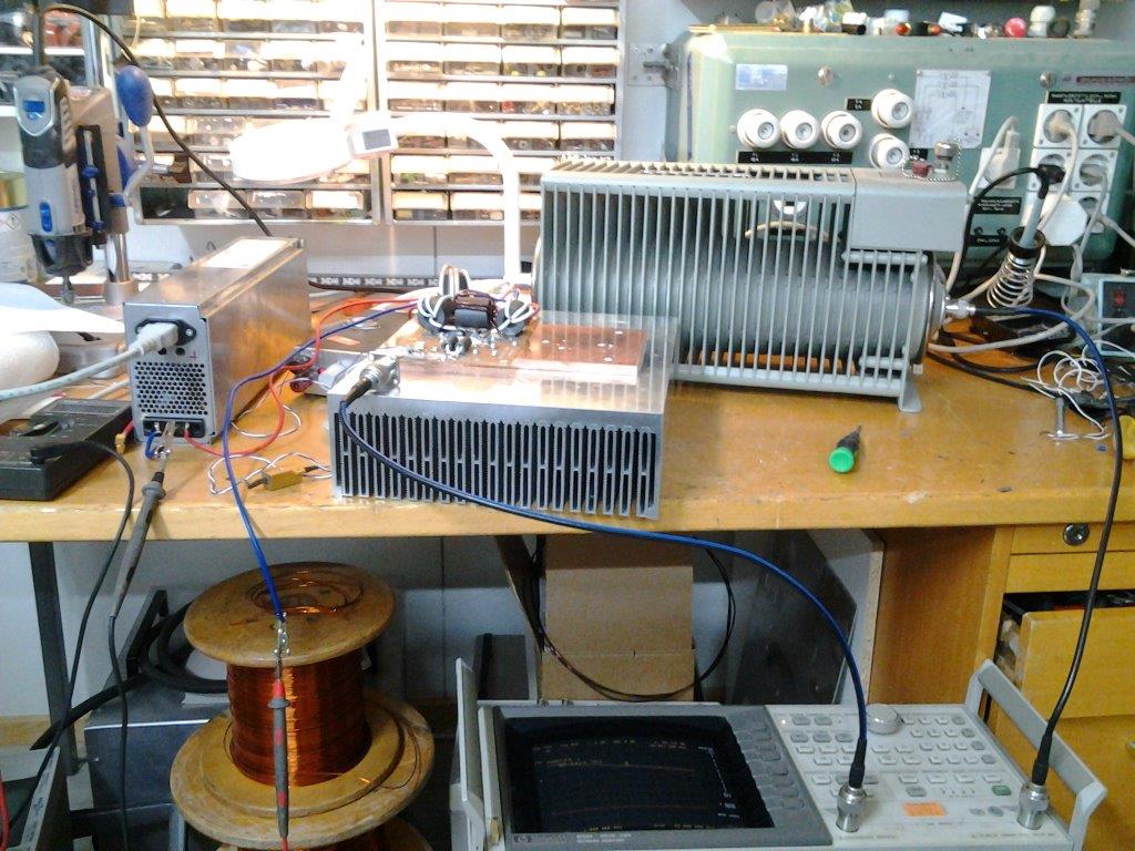
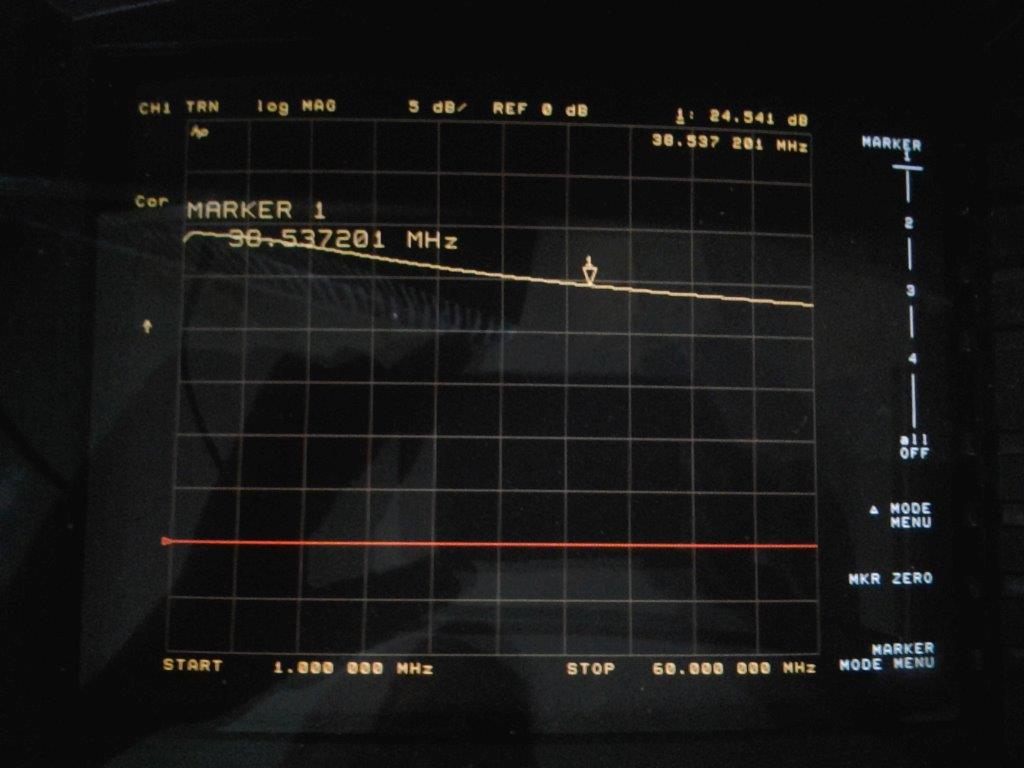
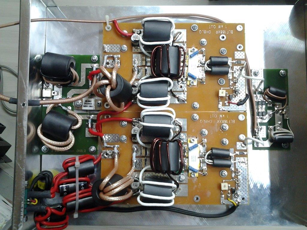
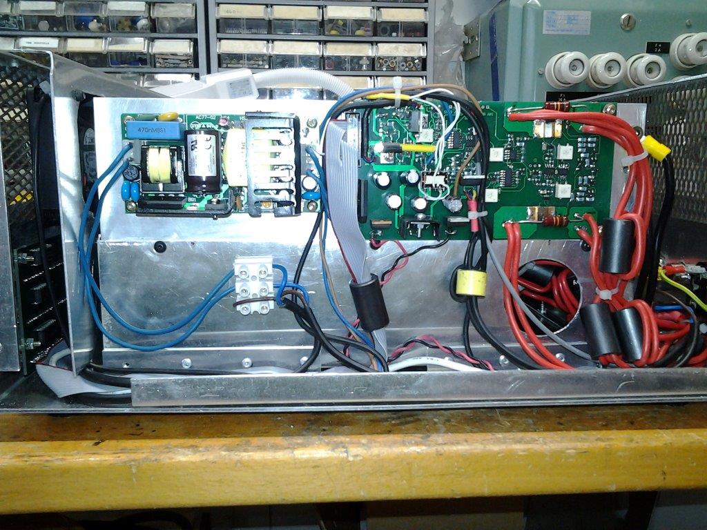
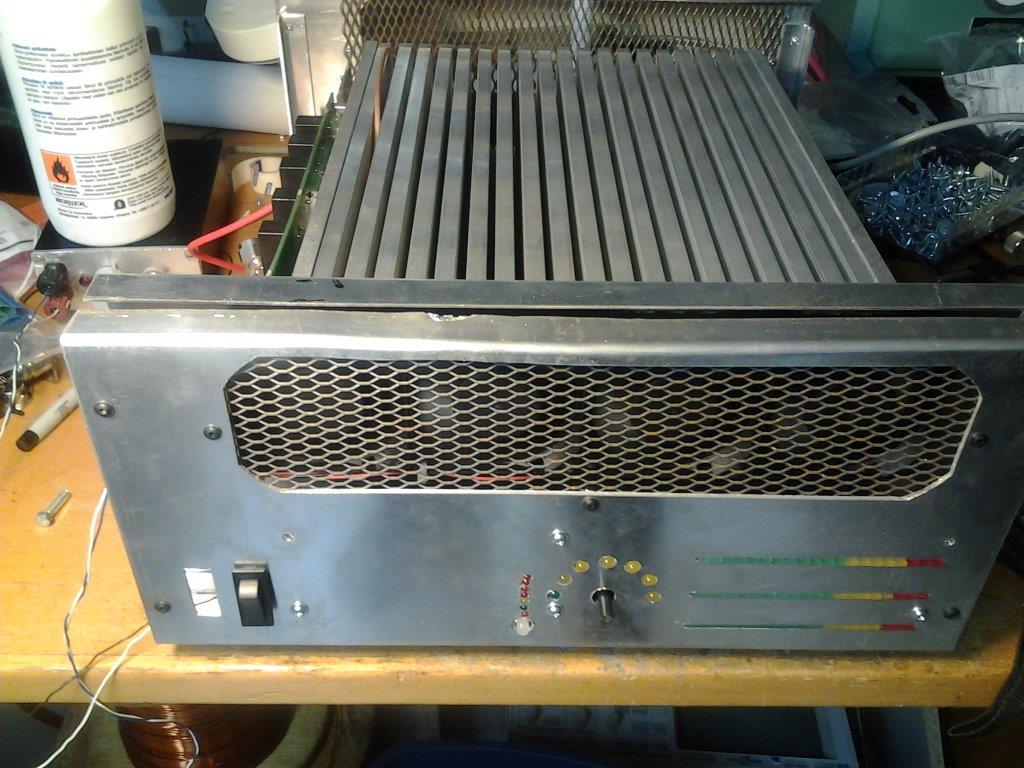
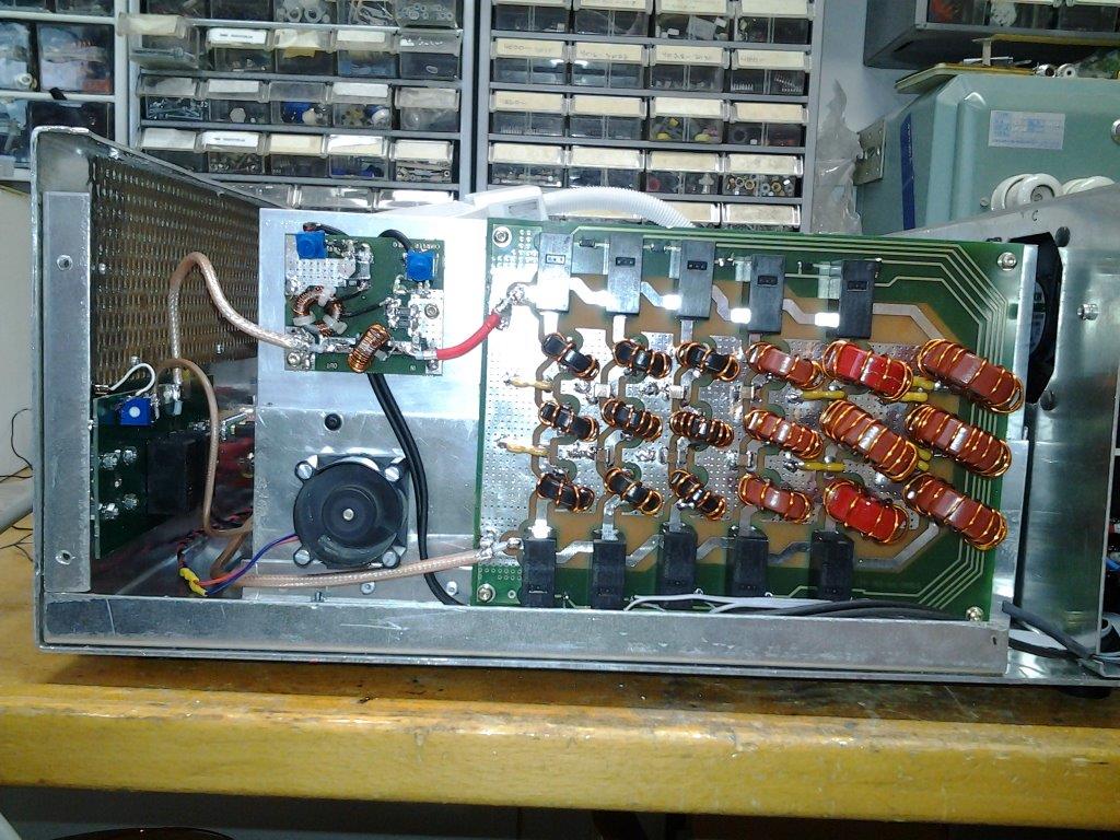
2xBLF188XR LDMOS HF-linear amplifier